
In this video, I provide a complete tutorial on how to assemble your own stair lighting, featuring block diagram, code overview, testing and final layout. Code and schematic can be found on this page.
Table of Contents
Problem Statement
Design Choices
Microcontroller
Input Device
Output Device
State Machine
Code
Schematic
Assembly
Frequently Asked Questions
Problems Encountered
Potential Improvements
Conclusion
Success Stories
Problem Statement
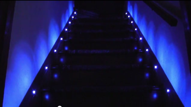
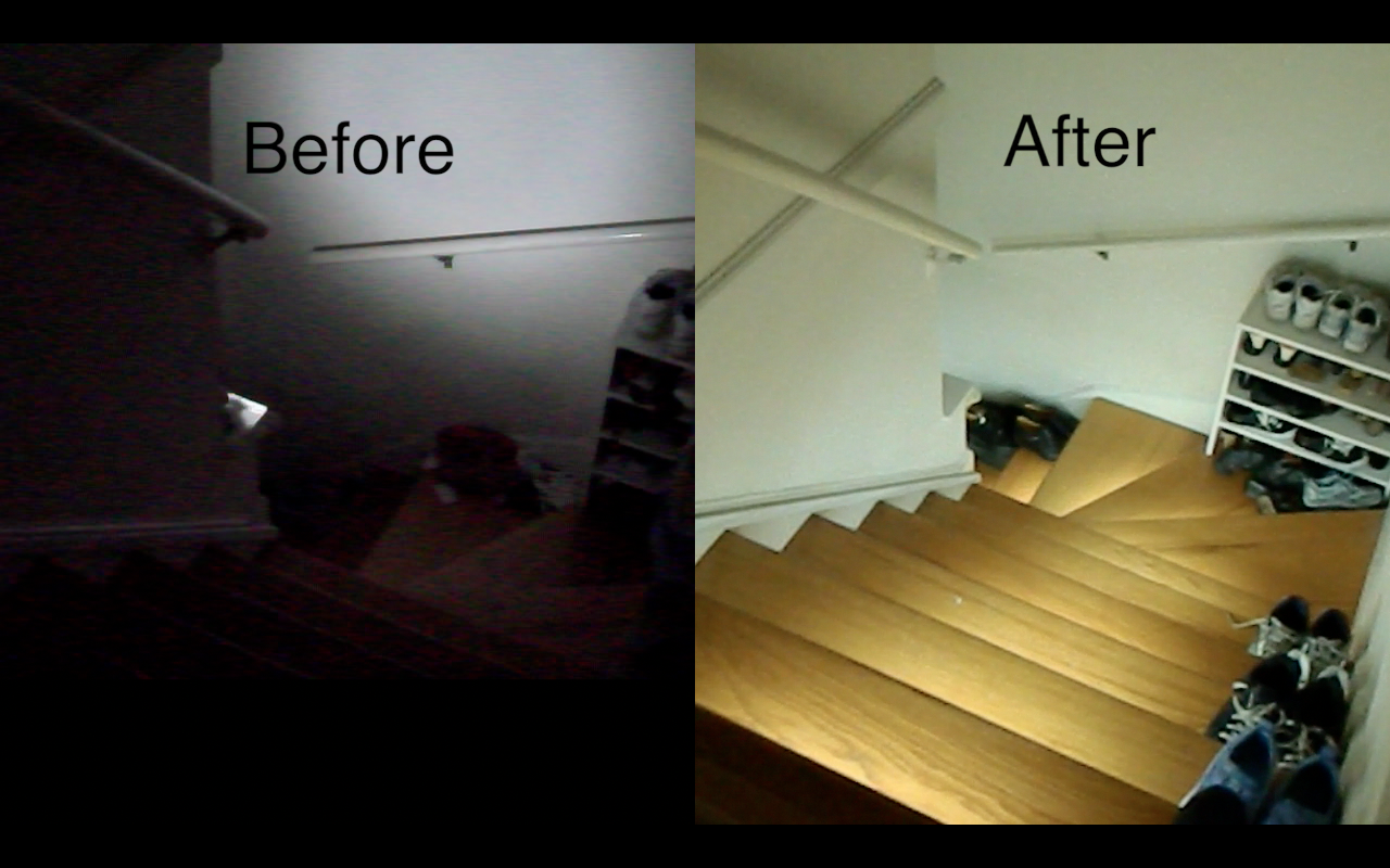
The stairs at night were really dark. It was bad enough that we had to put lights next to it. However, these lights shined in your face and not the stairs. I wanted to light up the actual steps. I really thought the German video was cool, so I aimed for that animation as my goal.
Design Choices
Microcontroller
I chose the ATmega328P firstly because it was on the Arduino. It had the hardware SPI, a ShiftPWM library and good enough speed. If I was mass-producing these, I would probably have chosen a microcontroller with less pins.
Input Device
I had some choices when looking for “person detectors”. I could have used laser sensors, IR beam sensors like they use at the store, or the PIR motion detectors. I initially wanted to use the laser sensors because they show absolute presence vs just motion like the PIR sensors, but they were too finicky. The laser sensors had to be positioned just right on the photodiode, and I didn’t know where to buy the IR beams. The PIR motion detectors actually work very well.
Update 2014-11-09 Since the time of this post there has been a new product in the Adafruit store called a “laser break beam sensor”. If the delay on the motion detectors is completely intolerable then you could try one of these: http://www.adafruit.com/products/2122
Output Device
For output devices, it was clear that I wanted to use the strip LEDs vs the regular point LEDs. I saw some previous implementations like this one and gawked because they didn’t even light up the stairs, only the walls next to the stairs!
This person lit up the wall.
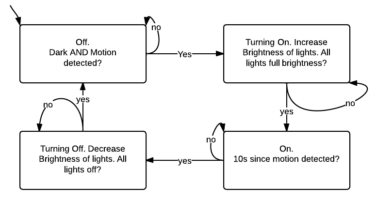
State Machine
Code
Code that runs on the microcontroller may be found on Github: https://github.com/androng/Shift-stairs
Here is a video to help you run the code:
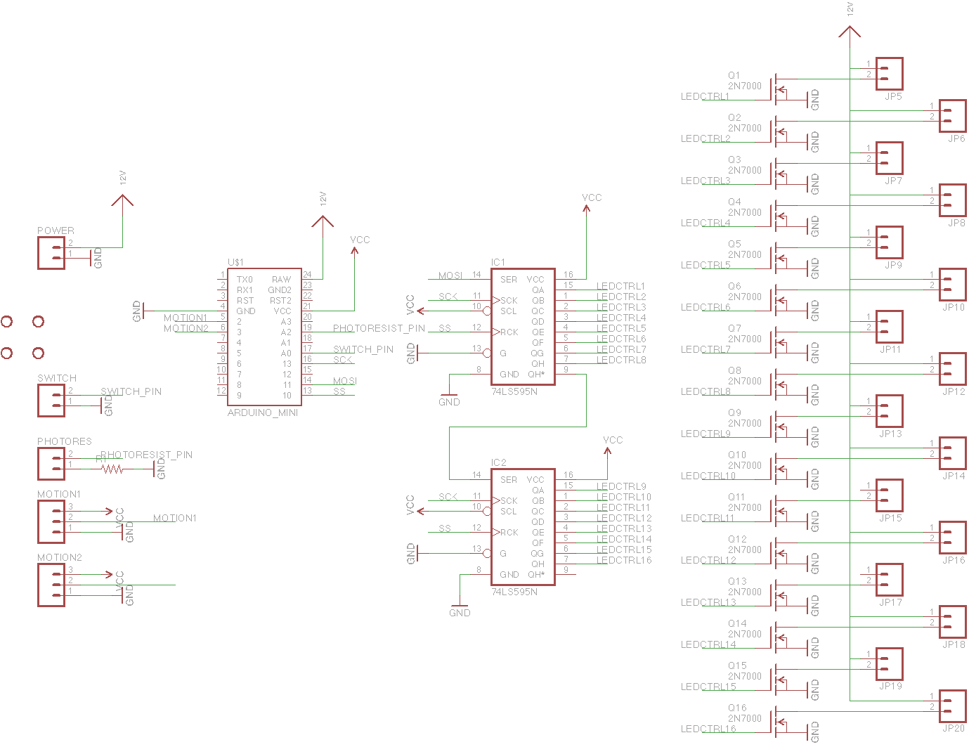
Schematic
I laid out a board but never had it printed. It should be completely functional, but have a look before you print it, especially the minimum distance between traces etc.
EDIT 2014-10-28: I have finally tested the board and it almost works! This was one of my first PCBs and I messed up in my definition of the 2N7000. As a result, you have to solder in the transistors backwards in version 1.0 of the PCB. In version 1.1 this is fixed.
The small rectangle on the left side is a matching through-hole resistor for the photoresistor. I recommend populating the LED headers at the bottom with 2×40 male headers and using black female jumper wires to connect the LEDs. Or you could modify the board to make screw terminals.
Version 1.3: https://oshpark.com/shared_projects/2aD8JaBR
Changes:
1.3
- Fixed “photoresistor always reads zero” problem
1.2
- Added footprint for voltage regulator just in case someone fries the one on the Arduino Pro Mini
1.1
- Fixed backwards transistor problem
- Added more labels for power, motion detectors
- Added labels for MOSFET source, gate and drain just in case you want to use a different MOSFET.


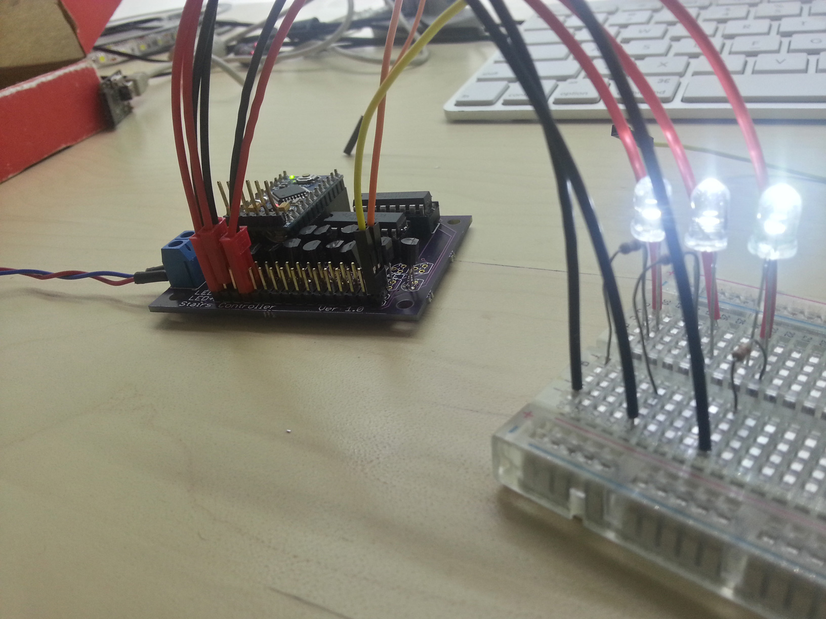
PCB with connectors. I originally wanted to use the red connectors but I didn’t realize they were too thick, so now I recommend the black connectors on the right side.
When you solder everything correctly, this should happen:
Assembly
You will need:
1x Arduino Pro Mini 5V, find on eBay
5m 3528 white LED strip, find on eBay
1x 12V 3A Power supply, find on eBay
PCB, $30 from OSH Park, see Schematic section for link
Enough wire for your stairs, you can also buy similar from Home Depot
2x PIR sensor or Laser sensor
PCB parts:
20x 2N7000 MOSFET or any other pin-compatible MOSFET. SOT-23 packages work well on the PCB too.
1x Single row female header
1x Double row male pin header
1x Single row male pin header
1x (Photoresistor and 10k resistor) (optional)
1x Switch (optional)
1x Screw terminal
2x 16-pin socket
2x 74HC595 Shift register
1x (LM7805 regulator and 0.1uF capacitors) (mandatory)
20x Female Jumper wires (one item comes with several wires)
Tools:
1x USB-to-UART
Soldering iron
Heatshrink and lighter – use the smallest size and cut into 3 pieces each
Wire stripper
Screwdriver
I recommend buying 2 or 3x everything in the “PCB parts” section in case you decide to start over.
Instructions
Assembly video and more detailed instructions coming in the future when I have time
- Assemble Arduino Pro Mini–solder male headers below on the long sides and above on the short sides
- Set jumper on USB-to-UART to 5V
- Connect USB cable > USB-to-UART > Arduino Pro Mini and program it with Blink sketch
- Assemble PCB (refer to photo in PCB section)
- Solder female headers in the “Arduino Pro Mini” slot
- Solder LED+ and LED- with double row male headers
- Solder side pins like “motion” “switch” etc with male headers
- Solder in sockets for shift registers and insert the shift registers
- Insert Arduino Pro Mini with FTDI header in the middle of the PCB
- (optional) Solder in regulator and capacitors
- Assemble LEDs
- Cut a female jumper wire in half
- Put heatshrink on the half-jumpers
- Solder half-jumpers to a 2-conductor wire, then solder 2 conductor wire to LED.
- Connect your jumpers to the PCB male headers
- Repeat step 5 for however many stairs you have
Frequently Asked Questions
How do I adjust the number of steps? Only nine of the steps turn on.
One of my lights doesn’t turn on/off or it flickers.
My lights stay on and never turn off.
One of my motion detectors does not trigger or has many false positives.
Problems Encountered
My choice of female headers as connectors for the LEDs was really bad. The headers are very secure, however all the wires are exposed and it is hard to place one in the middle. Other than that and the point-to-point soldering, I really did not have any problems.
Potential Improvements
Like stated in the video, I would have improved these things:
- Use constant-current LED drivers
- Add second override switch
- Feature: first step always on at night
- Route PCB with FTDI, ISP or Arduino socket on it.
- Made duty cycle vary exponentially with brightness to cancel out the logarithmic perception of brightness. I almost did this, but the effect was not noticable enough for me to spend a lot of time on it. I left it in the code as a large array. (it should be placed in program memory)
Conclusion
I accomplished the objective of lighting up the stairs as well as adding some extra features like daylight detection. After a long time, I finally completed the documentation and edited together the film I captured so long ago! I feel accomplished.
Success Stories
People like you and me have succeeded in banishing the darkness! Publish a video to YouTube, link to it in the comments, and I will showcase it here. Include a link to this page in your video.
Boštjan Perme 2017-02-27
Joshua Mauldin 2016-10-16
troysbucket 2014-11-25:

msvetec 2015-10-04

SG 2015-12-01

Gökhan ÜNAL 2021-07-05

Hey..It’s working.. (my friend’s gave me the Mosfet)
I used 9 led for the first time and everything’s ok.
Then I made up to 14 led.
I changed the code to
const int NUMLEDs = 14;
Problems :
– 14 led fade in then sequence.
– Then all led Stay on
I reprogram to 9 led, everything’s ok, back to normal
– All Led fade in then squence
– All led off
– motion sensor detect movement
– Led sequence
Did I missed something for the code ?
-Toby
Boards ordered, can’t wait to start the project. Already set it up on a breadboard and works well.
can you please give us the schematic to do the boards?, I live in Argentina and to order the boards i very complicated! thanks a lot!
The updated schematic can be found in the Github repository in the EAGLE folder.
Question about power supply?
So I completed the project. Looks good, solder looks good parts look good. Problem is when I hook up the 12 volt power supply the Arduino Pro Mini 328 – 5V/16MHz shorts out. Blows out the c106 resistor.
2ed Arduino Pro Mini 328 – 5V/16MHz the chip in the middle of the board melted.
I did add the one regulator and the 2 resistors.
Any idea what I did wrong or what it could be would be great. Thank you
If you have melting parts, then either voltage is backwards or is too high. I recommend doing an autopsy with a multimeter on VCC. I also recommend using a lower voltage power supply (5V) so that you can see if the LEDs work without it melting. I am not sure what you mean by C106. A picture would make it more clear. The external regulator is supposed to prevent the Arduino regulator from frying. It requires two capacitors, C1 and C2. I think you placed resistors instead.
Hey thanks for your help Andrew!, I’m having an issue that I hope you can help me with, the first 8 stairs work as they should, but the remaining 6 stairs just turn on and remain on. any thoughts?
Ah, I am glad that you were able to compile the code. Did you try changing the “NUMLEDs” variable from 9 to 15?
Yeah, I just tried that and no luck.
The number 8 sounds like a register issue–maybe the second shift register needs to be swapped? If you have a logic analyzer or oscilloscope, you can connect it to the legs of the second register to see if it is receiving the correct SPI signals when powering on.
Do the last six lights fade, ever? If they fade up and down like the former eight upon power-up, then it’s a software issue. If they never fade, its a hardware issue.
I swapped the second shift register and everything works great now! thanks again Andrew!
I just ordered all components and am very eager to try this project. I have in total 15 stairs and want to try the “1st/last light on” feature.
I hope that a more detailed instruction will come…. otherwise: Brace yourself, I ll ask questions.
Anyhow, I thank you for a great project page and for a hands on solution for my stairway. 🙂
Got my three printed circuit boards from osh park a few minutes ago. 🙂 Great way to start the week. Now just waiting for the tayda order to come in….
Bo Andrew brillant simple project.just waiting to get main board.what sort of code do we use for first last step always on?thanks
Cool, glad you liked it!
For the “first and last always on”, try replacing both instances of
ShiftPWM.SetOne(abs(l), brightnesses[abs(l)]);
with
if(l == startLight || l == endLight){ ShiftPWM.SetOne(abs(l), maxBrightness); } else { ShiftPWM.SetOne(abs(l), brightnesses[abs(l)]); }
did this work?
Hi Andrew no didn’t finished yet all parts completed but waiting for ordered PCB’s can’t wait to see working.many thanks
Hi everybody,
I use the version 1.2 of the board. I have some questions.
Do you have a picture of the board 1.2 with all components ?
I don’t know what is C1 and C2 ?
For the rest my board is ready, please help me
C1 and C2 are filter capacitors. Typical values are 0.33uF and 0.1uF.
If i dont have any capacitor ?
Is it possible to replace the resistor and photoresistor by a wire (switch) ?
You may leave the resistor and photoresistor unpopulated. They are optional. If you use a switch in place of the photoresistor, the stairs will not turn on.
OK and for capacitor ?
Can i leave unpopulated ?
Have you a picture of you 1.2 card ?
Thanks
You may leave the capacitors unpopulated. Hopefully the capacitors on the Arduino board itself will suffice. If there were no capacitors, then the output of the voltage regulator would oscillate, possibly causing unpredictable behavior on the Arduino.
I do not have a picture of 1.2–it is almost identical to 1.0 except for the transistors being backwards and the voltage regulator/caps.
Thank you !
I will finish my card, i send you a picture in few days
It’s works !
I used with 14 stairs. It’s so nice, now I must work with all wires ! 🙂
With pin 15 and 16, I want to light the banister, how I can switch on the 15 and 16 slowly ? (the same time like 1 to 14 switch on ?)
Thanks Andrew
I created a custom branch for you. It may or may not work. Try to download this code–does it produce the intended functionality? https://github.com/androng/shift-stairs/tree/banister
Would you mind posting a video of your results? Another commenter posted this one: https://www.youtube.com/watch?v=jM8gDLn-Woc
Thanks !
But doesn’t works !
I use 1 to 14 for my stairs, and 15 and 16 for banister.
When I switch on my board, All lights on, next all light off, and led 14 light on very very slow.
Next LED 16 is very low.
That all…
I apologize that you are not satisfied. Specify exactly what you want like “number of seconds to turn on”, “when the banisters should turn on” etc and results will come faster.
Difficult for me in english 🙂
So I want to use pin 1 to 14 of stairs
And I want to use pin 15 and 16 for banister. 15 and 16 at the same time
time to pin 1 to 14 to turning on = time to pin 15 and 16 to turning on
This is more explicit ?
thank you !
Andrew, Do you think it’s possible ?
It is definitely possible. If you are up to the task, you can try. I am very busy but will try again when I can.
Hi Andrew last question where in code we can adjust the speed of sequences for each step like slower/faster up and down.thanks
There are multiple ways to change the speed of the changing brightness. One way is to change BRIGHTNESS_SM_PERIOD. Higher period, slower changes. Another way is to change line the 5 in line 28 and 52 of “brightnessSM” to any factor of 255 (1,3,5,15,17,51,85). Does that help?
Yes that’s fine many thanks
Would you mind posting a quick demonstration video showing your assembled PCB and stairs? On Mar 30, 2015 2:32 AM, “Speedy Signals” wrote:
>
Hi Andrew will post but currently still waiting for my PCB to arrive as I am from UK.all cables and sensors are done also all LED’s installed Arduino programmed all parts waiting to solder.cant wait to test.many thanks
Hi Andrew stupid question how we can post a pictures here?got my PCB’s today can confirm All working fine great work.thanks
I don’t think you can post pictures directly, but you can definitely post links. Or even a link to a short video. On Apr 7, 2015 1:38 PM, “Speedy Signals” wrote:
>
Pictures as http://i60.tinypic.com/210hn6e.jpg
Cool! Now show it working on the stairs if you can.
Hi every one I have 5 asembled/programmed modules of version v1.2 all tested I’m in UK .can make package inc 50m of wire,2 sensors,night sensor.drop me a text on 07828671176 if interested.thanks
Hi Dariusz. There’s an issue on the v1.2 board where the photoresister is not connected to VCC. Can you let me know how you resolved it? Did you connect the outer photoresistor lead to VCC on the Arduino?
Andrew thanks
Great project Andrew, thanks for sharing, I like to use it for my stairs but instead led strips I will use single 10 mm led on side wall is you pcb and code good for that to?
I also need 24 channels for led-s is it enough to add just one more shift register and connect it like you connected original two?
thanks!
Glad you liked it! 10mm LEDs are fine. Just make sure that the current through the LED is less than 200mA. The code and PCB will handle it easily but you will likely have to use a lower power voltage. I used 12V for the LED strips but you will likely use 3 or 4 for the LEDs. And yes, 24 channels can be done with another [off PCB] shift register. You will also have to change the code to use three registers instead of 2 and maybe have to wire up more transistors. You could likely use two PCBs for this, or just extend my existing PCB. The EAGLE files are in Github.
Thanks for replay, I order parts and connect all on experimental board and change cod for 3 registers and 23 leds. Everything seams to work fine but led number 2 and number 14-23 are always on, when I activated sensor leds light up in right sequence and the ones that work all time changed brightness i little bit in that sequence because of power suplay, when other leds turn off the problematic ones get brighter. Do you have idea where can be the problem is it wrong connecting or bad elements?
I done it, here is video of my version
Hi. I saw your video of this project. I like your fade effect. would you mind sharing your code. I am struggling to change the timing in brightness.
how do i add an extra 5 led strips to the software
Add 5 LED strips by changing the variable NUMLEDs
Hi Andrew. Awesome project! I have the v1.2 board completely assembled. After uploading the code, all lights go on, then off, and then fade on/off as expected. If the switch is on, the lights stay on (as expected). An issue I’m seeing is that the photo resistor is reading 0 (always). I tried several photo resistors. Also, no motion is detected from the PIRs. (Testing with NUM_LEDS = 2). Any thoughts on why pins A2 , 2 and 3 might not register values?
Thanks,
Roland
Ah darn. My lack of QA has lead you to become confused and find a bug in the circuit board. The photoresistor always reads zero because it is not connected to VCC. This is the hardware fix: https://db.tt/CJpvfGkz.
As for the PIRs, I am not sure as to why they are not working. To troubleshoot, I would connect the PIR to a breadboard and put an LED on the PIR output. If the LED turns on then you have the correct pinout. If the LED does not turn on or the pinout turns out to be different than the Stairs board pinout, it’s a hardware issue. I checked the software and it seems ok. One other user has demonstrated his PIRs working.
Thank you for the reply Andrew. The link to the hardware fix is throwing an error “The file you’re looking for has been moved or deleted.” I’ll test the PIR output with the leds as suggested later today.
Here is the corrected link: https://db.tt/CJpvfGkz
Thanks Andrew. I tried to cut the circuit with a little knife but I think I’ll need to dig out the dremel – lol – those copper lines are tough. I’ll send pics of the modified board.
Photosensor is working with the new circuit. Thanks.
Issue with the PIRs I’m using is that they are HIGH by default and go LOW when triggered. Also the pins on these sensors from left to right are VCC, Ground, Output (Alarm). I’ll modify the code to see if it works. If not, I’ll get some more PIRs. Here’s what I currently have: https://www.sparkfun.com/products/13285
Ah see now that is critical information. WIth an open collector you will have to add
digitalWrite(MOTION_SENSOR_TOP_PIN, HIGH);
digitalWrite(MOTION_SENSOR_BOT_PIN, HIGH);
in the setup() function. This will enable the pull-up resistors. You will also need to swap the HIGH and LOW on lines 81 and 87. This will make it react to a falling edge and not a rising edge.
You will also need to swap the order of your cable to go VCC, signal, GND. I would just desolder the signal and GND cables and swap them.
Hi Andrew. Are you sure that someone was able to get both motion sensors working with v1.2? What I noticed is that Motion1 works fine when it’s the only sensor connected (returns HIGH for my sensor as expected). When a Motion2 sensor is added, both sensors return LOW. When only Motion 2 is connected, LOW is also returned but HIGH is expected. I’ll re-route Motion2 to digital pin 4 in case I have soldering issues or that pin is fried.
Tool Cool !! I added your code/hardware changes (as well as defaulting lastReadTopPin and lastReadBotPin to HIGH) and it’s now working as designed. I am VERY pleased! Thank you so much for your help. So glad to see that you continue to support your device and code!
I love nothing but the success of my readers. Would you mind helping the other readers by making a short video (2min) that shows your assembled board and your resulting stairs lights?
Can u upload a video of the assembly I’m trying to add able it but are getting stuck can you get a video out
Could you be more specific about what you are stuck on? You have to make it easy for me to identify the issue.
Awesome!!!! Simply awesome! How many of your components can cross over to SMD components. Also look into the 350mA AMC7135 CC regulator for your boards, you could even build a small board that connects directly to the LED strip rather than the controller board to reduce the overall footprint of the controller
Either way…very ingenious!
https://www.fasttech.com/products/0/10001705/1124200-amc7135-350ma-advanced-current-regulators-sot-89
You are right, I could indeed create a tiny controller and use a less expensive microcontroller etc. But this kit is aimed at beginners–the same person that I was three years ago. That’s why I use through hole components and ask them to order from OSH Park. Otherwise I would just use SMD components, enter the stair lighting market and sell the board myself for a profit.
Just have to say this is one of the coolest projects I’ve seen in a while. Putting the items into an ebay cart, and adding it to my project list.
Thank you!!!
How’s the project going? Would you like to show off a video?
What is the maximum amps can I run off this controller? I would like to use 4 led strip lights and am not sure if controller can handle the total amps needed to power the leds
The 2N7000 MOSFETs can handle 250mA each. You can replace them for a pin compatible version. After that, the limiting factor would be the power PCB traces. I made them as thick as possible but I have never empirically tested them. I believe the brightness is logarithmic with respect to power, so don’t use too much current because there are diminishing returns.
Ok, thank you for the quick response. I will have to do some testing and see what I come up with. I followed your instructions and the controller works perfectly. Thank You 🙂
I am so glad the board works. If you make a video demo, I will showcase you in the post.
Hi Andrew, quick question if I may, When verifying on the Arduino program, I keep getting an error: Arduino: 1.6.5 (Windows 8.1), Board: “Arduino Uno”
Shift_Stairs.ino: In function ‘void loop()’:
Shift_Stairs:110: error: ‘brightnessSM’ was not declared in this scope
Shift_Stairs:110: error: expression cannot be used as a function
Shift_Stairs:111: error: expression cannot be used as a function
‘brightnessSM’ was not declared in this scope
This report would have more information with
“Show verbose output during compilation”
enabled in File > Preferences.
Is this an easy fix? Also, can this be done before programming the Arduino Pro Mini?
This error indicates that you did not download and unzip the files correctly. Did you click “unzip all” and rename the sketch folder? The installation video above was done on OS X but the procedure is almost the same with Windows.
I will have another go at it, I’m also on Windows 10, so hopefully that wont be a factor.
It Verified! Thank you Andrew. Now I can just edit the code as per how many stairs I’m using and then verify again correct? Then I upload to Pro mini?
Yes. Change the NUM_LEDs constant.
Hello Andrew,
First of all, great project! My parts are already ordered except Arduino mini.
I wanted to ask you is it ok to use Arduino Uno R3 instead of Mini or separate ATmega microcontroler? Because I have one spare at this moment so I was wondering if I can use it?
I’m glad you ordered the parts! Now comes the hard part of actually assembling them.
Yes, you can use an Uno instead of a Pro Mini. They have both use the same microcontroller. However, I don’t recommend using the Uno because you will have unsecured air wires from the Uno to the stairs controller PCB. This will make your project bigger, uglier and less robust for $4 in savings. Save your Uno for prototyping elsewhere. Buy the 16MHz 5V Pro mini.
Hello, can you Andrew or anyone else trying this project recommend a power supply? Also, is it a big deal if I’m using a 1uf capacitor rather than a .1uf? What type of capacitor is best (ceramic, electrolytic….)? What voltage as well please?
Buy any 12V power supply that is rated for 1A or more. You should use capacitors recommended by the datasheet. Capacitance too high may come with too high of an equivalent series resistance and capacitors too low won’t provide enough capacitance and might cause the regulator to oscillate. But I have not tried it. Any material should be fine. Just don’t get the polarity wrong with electrolytic or tantalum. The capacitor needs to be 12V+ on one side and 5V+ on the other.
Hi Andrew, thanks for this project it’s fantastic!
I have a problem actually, when I power up the board, the sequence is running fine and all the LED are powered. But at the end when the sequence is finished, some led are still showing some luminosity. So I check with the multimeter, and they are all showing different voltage 0, +7, … If you run the sequence the luminosity is ok on each strip so the problem are located on the idle time.
So i’ve exchange the cable between two strip and the issue appear as well. Potentially the 2N7000 are defect, but this is a lot just for a small board! (Static discharge damage?)
Also when i don’t have the PIR connected, if i touch one of the pin with my finger, the sequence start … really weird.
IDLE Pic 1: https://www.dropbox.com/s/sasbk78e5033xc9/20150829_195738.jpg?dl=0
START Pic 2: https://www.dropbox.com/s/yabgca94flynue6/20150829_195726.jpg?dl=0
Funduino DEAD: https://www.dropbox.com/s/6d7vv548ukknyo0/20150829_020949.jpg?dl=0
PS: There is the same issue on two board.
If you have any advice will be appreciate 🙂
Thank you
Thanks for assembling the board! It makes me feel better knowing someone finds it valuable. It looks like you assembled it correctly.
From what I gather, it seems like a power supply issue or a microcontroller issue. You can try removing half of the strips and seeing if the idle light is better. If so, then the power supply might not be supplying enough current. You can also try measuring the VCC pin of the Arduino and shift registers. If it dips below 2.0V then it might trigger undefined behavior. I would add the optional 7805 regulator.
I also notice that in your photo, you do not have the GND wire of the FTDI connector connected to the Arduino. At least it’s not on the end pin.
The behavior of your finger triggering the animation when the PIR is disconnected is from static electricity. The input pins of the Arduino only have a few pico Farads of capacitance. These can be charged easily by your finger. You can prevent this with a pull-up resistor but I did not enable it in the code because I was not sure how strong the PIR output would be.
You can also try using another Arduino. It is possible that one could be defective. Try these things and let me know.
Thanks for your advice 🙂
So there is my tests:
I’ve 5.03V on the Funduino and same for the two register.
There is only one strip connected at this moment and if I connect it on the stairs:
1, 7, 8, 10, 12, 15, 16 it’s working perfectly fine.
2, 3, 4, 5, 6, 9, 11, 13, 14 are not working and showing some variant luminosity (Different luminosity per led for the same LED strip).
Tested with an another strip to be sure and this is the same problem for the same stairs.
I have two power supply which I can select the voltage but the problem still remain the same.
1. 12V – 5000mA ( 6V to 15V) Tested with 9V and 12V, same issue.
2. 12V – 3500mA (9.5V to 20V) Tested with 9.5V and 12V, same issue.
I’ve exchanged as well the two shift registers (tested with 3 different set) same issue.
Then I buy some extra 2N7000 to try on the latest board but of course I forget the regulator!
So at the end the voltage seems to be fine, maybe the Arduino as you said, but there is already the second, the first one has burn with the 12v ^^.
Greetings from Amsterdam!
How strange. It works with seven lights and not with the remaining nine? You can try to change the power rail to 5V instead of 12V. You can also use an oscilloscope to check the power lines and the SPI lines for any erratic behavior. Perhaps an Arduino from a different supplier? If those don’t yield anything then I don’t have any more suggestions.
Hi Andrew!
First of all i have to thank you for everything. It’s working now with EXACTLY the same components and power supply. The only thing, I’ve borrowed an Arduino Uno which I pin on the PCB (And all the leds was flashing). After that, when I’ve plugged back my Mini Pro less than 30 secondes later, everything works fine now (Even if I turn on/off or reupload a new code).
Looks like a GND somewhere that the Arduino pro (Copy) can’t handle or something like this?
Anyway, this will be install on my new house, so I hope to take a video for you 🙂
Cheers,
Pimousse
I’m so glad you were able to get it working. I am still not really sure what the issue was. Maybe the signal was noisy. I will add some GND planes to the PCB now that I know how to do that. Thanks for helping reply to comments.
Hey Andrew, I was wanting to use higher powered LEDs their power supply is DC12v and but they are .3W LEDs. How can I make these work with the arduino?
The higher power LEDs should be driven with constant-current LED drivers and the matching power supply. You will have to wire the gate of each MOSFET to the input of the constant-current supply.
You can forgo the constant-current drivers and just use a MOSFET or BJT, but it is riskier because you have to do some calculations. The 2N7000 MOSFETs would blow up, so don’t use those. I actually have some of the calculations detailed here: https://speedysignals.com/2013/06/27/how-to-switch-a-transistor/#Transistorselectionprocess
Ok thank you, another thing I thought about, if I was going downstairs, the leds would light up backwards I guess. Is there a way to have them sequentially light up both ways?
It sounds like the motion detectors are wired backwards. Try swapping the signal lines of MOTION1 and MOTION2. The firmware is programmed to animate the lights in both directions.
Oh ok, it was just a theoretical situation because I wasn’t aware it went both ways. Thank you! I look forward to starting this project!
Sorry for the tons of questions. My stairs have two switches, upstairs and downstairs. I’d like to have the override switch in the downstairs switch box sharing it with the actual hallway light. I was going to use an adorne switch box with one of their switches. Would that switch be compatible with the assembly?
Yes, you can wire a 3-way switch. But instead of the ends being “hot” and “neutral”, use the two terminals that are labeled “switch” on the PCB.
If you need an example diagram, let me know.
Sure please do. I think I get it but I want to be sure. Here are the LEDs I will use, let me know if they work without having to change the mosfets. http://pages.ebay.com/link/?nav=item.view&alt=web&id=271897972751&globalID=EBAY-US
Yes, those lights should work. Go ahead and buy them.
Here is the diagram for the 3-way switch: https://db.tt/fQBJgKZL
How many mosfets do I install? How do I determine that number?
You install as many MOSFETs as you have stairs
which side of c1/c2 is positive/negative, I have a 1uf 50v capacitor but not sure how to insert it
Of the four holes of C1 and C2, the outer ones are positive and the inner two are negative.
last question, I am trying to add the codes but I get the error message about brightnessSM. Arduino: 1.6.5 (Windows 7), Board: “Arduino Pro or Pro Mini, ATmega328 (5V, 16 MHz)”
Shift_Stairs.ino: In function ‘void loop()’:
Shift_Stairs:110: error: ‘brightnessSM’ was not declared in this scope
‘brightnessSM’ was not declared in this scope
How do I input the value?
not sure why that happened but it works now, only problem is that it has an error uploading the codes. The mini is soldered to the PCB and the right pins are connected to the right stuff on the UART.
Arduino: 1.6.5 (Windows 7), Board: “Arduino Pro or Pro Mini, ATmega328 (5V, 16 MHz)”
Sketch uses 10,206 bytes (33%) of program storage space. Maximum is 30,720 bytes.
Global variables use 852 bytes (41%) of dynamic memory, leaving 1,196 bytes for local variables. Maximum is 2,048 bytes.
avrdude: stk500_recv(): programmer is not responding
avrdude: stk500_getsync() attempt 1 of 10: not in sync: resp=0x65
this is repeated 10 times. When plugged in none of the LEDs on the arduino or the UART are blinking. Does there need to be a power supply to the PCB?
Oh good it compiles!
The error avrdude: stk500_recv(): programmer is not responding avrdude: stk500_getsync() attempt 1 of 10: not in sync: resp=0x65
can mean one of multiple things. Your board is selected correctly but your programmer might not be. Your Arduino must be powered on while it is programmed. The PCB does not need additional power if it is being supplied by your programming cable. Since none of the LEDs on the Arduino are on, it is a power issue. Is something shorted?
1. The board doesn’t need to be turn on, only your Arduino.
2. You have selected the right board, but did you select as well the right programmer? Tools => Programmer => Arduino as ISP
3. I’ve been stuck as well on this too, but i don’t have the automatic reset wired.
– When you see that the code is compiling on the software, press the reset button on your arduino at the same time, then your UART will start to blink and upload the code.
4. Just in case (and if somebody else are reading), GND to GND, RX to TX, TX to RX, 5V to VCC
All the lights flash now, I had one of the shift registers backwards. I get this error code when uploading. I selected AVR ISP,
avrdude: stk500_recv(): programmer is not responding
avrdude: stk500_getsync() attempt 1 of 10: not in sync: resp=0x52
avrdude: stk500_recv(): programmer is not responding
Try taking the Arduino out of the controller board and uploading code. The RX/TX lights should flash, not just the RX. The Arduino Power LED should be on. If the code uploads when the Arduino is out of the Stairs PCB, then it is a PCB problem. If the code does not upload when the Arduino is out of the Stairs PCB, your programmer is probably wired incorrectly. A picture would be useful.
Does your programmer look like this or close to this? http://www.grifo.com/PROG/HBI/FOTO/AVRISP.jpg This programmer is only used when you shift-click the “Upload” button, changing it to “Upload using programmer”. If you do not have this kind of programmer, the “AVR ISP” option is irrelevant.
And of course the most likely cause of all is that you have not installed the FTDI drivers for your operating system.
Ok, I’ve never really had success removing solder, I’ll have to invest in the suckers. Are the FTDI drivers manually installed or does my computer do it for me? I will post pics this weekend
The FTDI drivers must be manually installed on both Mac and Windows. Only the older programmers are FTDI. I believe the newer programmers (with an ATmega16u4) don’t require any installation.
Everything works great now and codes uploading and LEDS are lighting up. Last issue is the photo resister, whether it’s dark or bright in the room the LED’s still light up
For the photoresistor you have to 1) place a 10k resistor in the resistor slot of the PCB and 2) identify what light level you want the stairs to trigger at. For example if you want to trigger at sunset then you would measure at that time. To measure, put “Serial.println(analogRead(PHOTORESISTOR_PIN))” at the top of loop(). You then run the program, open the Serial Monitor and copy the value you see into “LIGHT_THRESHOLD” on line 25.
Great, everything was working perfectly until I did the final plug in, suddenly the blue LED on the arduino went off and the LEDs on the stairs stay on. The red LED on the arduino still is on thlugh
Were you able to get this working? I was not able to discern much from the last information you provided.
No I was not. The only issue I found was that the capacitor was 1uf and not .1 I switched it out and still no result. Maybe something is wrong with arduino? Can you link me to a website that sells authentic arduinos? Maybe I’ll just restart
Before I completely restart, I would like to test the arduino on a breadboard with new components. Can you somehow guide me through how I should hook this up to a 830 point breadboard? Give me an email or something.Thank you.
Of course. Here is a high quality tutorial: https://learn.sparkfun.com/tutorials/using-the-arduino-pro-mini-33v For the stairs I recommend a 5V version so pick 5V on the “Board” menu.
Ok I see, I would need to know where each pin on the arduino connects to what on the PCB. Where do each of the three mosfets connect to and that sort of thing.
The schematic is on the page. The MOSFETs do not directly connect to the Arduino. The Arduino connects to shift registers and those control the MOSFETs
After trying everything here it is, still not uploading.
https://www.dropbox.com/sc/ng7g6x1rcfbkq3g/AACGG6gx6OL79CUnpJLoWPNOa
From the photos I can see that your DTR line is not connected. The Arduino will not reset and will never enter programming mode. I would connect that–otherwise you can time the reset with your finger on the reset button but its a little harder.
Why would I need to install a regulator, capacitor, or resistor? I know they’re optional but what’s the use?
The capacitors and regulator are for substitution in the event that the small regulator on your Arduino fries itself. The resistor is to provide a light level reference for the photoresistor.
Hello Andrew! Thank you for your job. The project is great! Everything works perfect.
Don’t you think to add some functions to this controller?
It would be good to add the function of switching on towards to each other when both sensors activate in the same time.
Also in the process of switching stairs off if any of sensors activates switching off will stop and switching stair on will start.
I am glad you liked it. Did you assemble one? I would love to see a video.
There are always many more things to add to a software application. But each of those features takes time to test and integrate. If you wish, you can code the changes and submit a pull request into the repository.
Unfortunately I didn’t finish highlightning of stairs. Now I have one problem with it. When the LEDs switch on two LEDs in the middle switches on automatically earlier than other ones.
It is showed on the video below.
Could you please help me to solve this problem?
Unfortunatly now I don’t have enough knowledge in programming to add new functions in the controller work.
I tried change shift registers and added capasitor 0.1mf but it does not produce results.
I am not sure what the problem is at this point. The circuit looks almost completely functional. The “two LEDs in the middle” issue may be a problem in the ShiftPWM library. I would have to spend time debugging the software, starting with some printlines of ShiftPWM brightness values when the animation starts.
Ok Andrew! Thank you. I will to try.
Hey guys, can anyone tell me what capacitors you are using? Be specific please. I’m still having a very bad problem with frying my Arduino’s. I’m on my 5th one now, very frustrating. The last go around my regulator was extremely hot to the touch. Is that right? Also I’m using an old 12v 2.5a laptop power supply, should I use this or do they make a hobby power supply version? Every time we add power, after maybe 10-15 seconds the Arduino smokes and sparks. Thanks for any help.
Hey Niras, can you be more specific? Do you have some pictures and the reference of your regulator/capacitor (Or a direct link of your model) and also your power supply? I’ve fried two Arduino, but it was my fault, I’ve inserted on the wrong way. The Arduino can handle the 12v without the TO-220 and the capacitors, so it should be something else. Have you tried only the Arduino on the second board without any other components?
Arduino without the regulator, output of my power supply 12v / 5A .
Thx Pimousse, what type of capacitors are you using on your board?
Pimousse. Question. I would like to know the exact capacitors your using. A picture of them would be great too. I appreciate
Capacitors: 0.1uF 104 50V Monolithic Ceramic Chip Capacitor (1$ on ebay for 50pcs).
But as Andrew write on this tutorial, Capacitors and 7805 Regulator is OPTIONAL!
Did you try buying an Arduino from a different vendor? Vendors use different components on Arduinos and with regulators it is hard to tell what is on the inside. Make sure you orient the Arduino correctly too; the Arduino FTDI header should be near the middle of the stairs PCB.
I’m wondering if there might be an issue with the OSH Park pcb’s? I mean same problem on two different boards?
hello, I want to build this into my stairs at home, I have 14 steps until 60cm to 1m long . have never done anything with coder and stuff so the question is if you could fix codningen to me? and are all in the purchase list up to date ?
Yes, everything on the purchase list is up-to-date. I don’t know what “codningen” is but I can help if you make it easy for me. Good descriptions and pictures of your problem help.
i meant coding, i haven´t started anything yet or bought anything yet. should i buy 2 set of evrything? and do u got some pictures of the moderboard so i now what to do?
Hi Mr Andrew
I am going to work with your project for my new home I need your supports to complete this,
I can be used any of mosfets coz 2N7000 is not available
Thank you.
Hi Mr andrew,
I have a doubt , I am planing to use in 17 stairs one strip 80 CM long and I checked the current id 0.4 A so I required 17X0.4= 6.8 A . If I use a 12V 7A power supply will effect any problem to my arduino or I need to use any current regulators please advice me
As far as I know it should work. Just from the number “12V 7A” I don’t know whether it will work reliably. You will have to pick another N-channel MOSFET because the 2N7000 can only support 200mA drain current.
I done it, here is video of my version
Hi… I’ve ordered all of my items they should arrive by the end off the week… I was wondering if you had made a casing for the pcb if so how have you made it… Al so I have pir sensors that need a casing is there a way I could make one or a website I could by some off ?
Cool! Keep me updated. I will soon add you to the success stories.
I have not made any casing for the circuit. When I first made this, I used a project box from Radioshack and drilled holes. I also left the PIR sensors bare on the stairs. It was not very pretty, but it worked. I did paint the box so that it blended in with the wall. I am not an expert so the best I could do is make a case in Sketchup and 3D print it.
Okay thanks…. I was thinking of using blank socket casings for the sensors… and a double socket casing for the pcb but till I receive the pcb I wouldn’t know if it would fit !
hey, i want to order this now but how much is the total price for 1 set of all? and the female jumpers u said buy 20 but in the pack you linked is 40. do u mean buy 20 packs of the 40s?
and do u got a link for laser sensors? thanks i relly want to start and make this happening. 😀
The price will vary depending on the big items like the LEDs you choose. The laser sensors have been discontinued from Adafruit and I know of nowhere else to buy them, so you will have to use the PIR motion sensors. The female headers come as double-row, where one “row” is 20 pins. So 2×20 = 40 pins in one double-row header. You only need to buy one double-row header but I recommend two. Feel free to ask more questions.
Hey, i will use the led strip going to need 12meters for 14 steps.
Also if i get the pir sensor how do i connect it to the board if i put sensor in stairs?
The PIR sensors have three wires: VCC, GND and signal. On the PCB, connect VCC to +, GND to – and the signal to the middle pin.
I ment more in the wall. How do u get the pir in walls or laser? Can you link me pir sensors and laser sensors please? Thank you cant wait to start
I would buy the PIR sensors on eBay. The ones I used are no longer sold. To mount them, I would drill a large circular hole into a faceplate, glue the sensor edges to the faceplate with the lens sticking out from the drilled hole. Then mount the faceplate on the wall however you think is tolerable.
What do u think about pir motion like Hc-sr501? Found it on ebay but will it work if i put this in the wall or is it not good enough?
That detector should work. But they each use 65mA, which is a lot. I would recommend placing the optional regulator and capacitors.
Well all my stair controller came yesterday afternoon, so hopefully gonna crack on today and get it all up and running, will post pics/video when done 🙂
I wish you luck. I tried to make it easy but still DIY so you could feel proud.
Okay have a problem, I uploaded the coding a a few days ago before I soldered everything on, now I’ve put all the components on and soldered when I plug the main adapter in the arduino board flashes red what does and nothing works ? I’ve tryed uploaded the program again and all I get on the screen is brightnessSM was not declared in this scope?
The error “brightnessSM was not declared” means that you did not open the files correctly. The brightnessSM file is not visible to the compiler. You have to click “Shift-stairs.ino” and follow the instructions in the post on how to download the code and rename the folder etc. The screencast was done on OS X but the Windows procedure is almost the same.
I downloaded the zip changed the name to Shift_Stairs open the folder when in that folder theres another folder that says shift-stairs-master but I had already changed the name of it, I try to rename this folder but wont let me so I open that folder and I have Shift_Stairs but no Shift_Stairs.ino when I open Shift_stairs it opens in arduino but only as one tap instead of 3 like in the video, the arduino bored flash’s with a very dull red light when I plug it in to the mains to see if it works ?
Okay I’ve finally programmed it, now when I plug it in to the mains nothing works but the arduino board flashes red, does the regulater have to go in a certain way, I’ve not put the photoresistor in just yet as I’ve gotta sort a casing out for it
Okay this is what I get when i plug in to 12 v power supply… nothing happens apart from this red light on the arduino board just flashes….
This picture really helps. I don’t see a second capacitor on that regulator. I also notice that the shift registers are placed backwards. I would recommend programming the Blink sketch onto the Arduino just to know that it is working.
Okay I bust my other arduino plugged a 12v 3.5 amp in and fried it so I got another one, now this light stays on but still no lights come on and don’t know what the problem is
Hello Drew,
As many have said, this is a wonderful project you have done and I thank you for sharing it with the community! I’m glad to see that you’re quite active on the posts since you’ve created this project.
I too like many here am going to try this out, and hopefully I can accomplish this as I am quite new to the Arduino world.
I would like to ask, the capacitor that you have listed in the parts list. Is it 1uF or 0.1uF? (or are they the same?)
Thanks,
Snap
Good! This project is aimed at total beginners who know how to solder. A larger output capacitor can handle higher transient power spikes so I would use the 1uF. If you have hardware problems make sure to take well lit pictures
Drew,
Thanks again for the prompt response! I have purchased the same type of capacitor like Pimousse did (1uF Monolithic Ceramic Chip Capacitor). Will this work for this purpose?
I appreciate your time and knowledge.
Cheers,
Snap
Yes, the ceramic chip capacitors should work. They have a lower chance of exploding.
Make sure C1 can survive 12V and C2 can survive 5V.
“Make sure C1 can survive 12V and C2 can survive 5V.”
Can you elaborate on this? I will be soldering the 1uF caps on both C1 and C2 at the same time. Do you mean that I should solder one > test > check > then solder the second > test > and check?
I will be using a 12v 2.5a power adapter.
Thx,
Snap
You don’t have to check manually. When you buy the capacitors, they come with a certain voltage rating. Make sure that it is higher than 12V and 5V. They will explode or short otherwise. For example, this capacitor has a voltage rating of 50V. http://www.taydaelectronics.com/capacitors/monolithic-ceramic-capacitor/0-1uf-50v-multilayer-ceramic-capacitor.html
Dear Andrew,
I saw your video and loved it. I never worked with Arduino and this will be my first project, however, I have couple of ideas which brings up couple of questions:
1) Can I use Teensey 3.2 instead of arduino Pro Mini instead? I believe Teensey will give better ability to add complex functionality since it runs at 64 mhz.
2) Can I add any type of music function or additional software to it to make a dynamic staircase lighting. I am trying to make stairs light up and works like this one https://www.youtube.com/watch?v=HmUtPwTrmPM
Obviously, I need to use addressable led strips instead of just RGB.
Any advice or help that would be appreciated.
Thanks,
Joe
Every viewer that loves my video brings pleasure to my consciousness.
You can add all kinds of features to your stairs. I don’t know how much electronics experience you have but if this is your first time programming a microcontroller then I would not recommend coding music and RGB patterns. You are correct in that a Teensy will allow you do more than an Arduino. However, the PCB in the blog post is wired for an Arduino Pro Mini driving shift registers and MOSFETs. If you want to use a Teensy with RGB strips then the PCB becomes completely useless. An RGB project is a lot more expensive and harder to program. But the final result is much cooler.
I also have to note that the Teensy does not have enough memory to store audio. You would either have to use heavy compression, ChipTunes or buy the Teensy Audio Shield.
Hiding the wires?
I thought I’d better start a new post for this topic. Can I ask everyone that has created and implemented this great Stair lighting to comment on how they hid the wires?
The underside of my stairs are drywalled, and I wanted to see how you all hid your wires so that I can have some reference/ideas.
TIA,
Snap
hi snap, I will be using truncking to hide my wires run the mains cable under the carpet, I’m plnning on using socket casing with blank tops to hide my stair controller and also to use on the sensors but drill a hole for sensor bubble to sit in nicely,
Thanks for the response Mark. Any others?
At 0:00 and 2:30 in the video you can see some wiremold. The only wires showing are from the motion detectors at the top and bottom of the stairs. http://www.monoprice.com/product?c_id=105&cp_id=10520&cs_id=1052005&p_id=8288&seq=1&format=2
If you can access the underside of your stairs then you have a lot more options. I had to run the wires on the side.
Drew, I thought about that but I wanted to flush the install so there are no traces showing. Let me do some googling.
Thanks for the responses guys.
Okay so I fried my last arduino buy putting 12v 3.5 amps in… so I bought a new one… now the light on the arduino board stays on…
I would try some incremental troubleshooting. First, remove all the electronics from the carpet. The carpet can promotes static electricity buildup.
The red LED indicates that the Arduino is receiving power at the correct voltage. This is good! Remove the Arduino from the PCB and connect it to the programming cable. Program the “Blink” sketch. If you are able to program and the second LED on the Arduino blinks, then the Arduino is functioning. If not, the Arduino is broken or your Board/Serial Port are incorrect.
Place the functioning Arduino back into the PCB. If you can still program, great! If you cannot program, something is wrong with the PCB.
Sorry for all the questions, I’ve finally got the board to work, problem is the lights stay on all the time, even when they power up they don’t Don’t do anything apart from come on, I’ve changed the registers but still stay on, I have my 3rd arduino board coming Monday or Tuesday I’ll try that one when it comes but in the mean time what else can I do
From the software perspective, the only thing that could cause “always on” behavior is the switch pin being LOW. From hardware “Always on” could be caused by backwards transistors, permanently high MOSI line, P-channel MOSFETs, and more. Could you take a well-lit picture?
Here’s the photo,
From the photo I cannot see anything wrong. I will play with my setup and see if I can diagnose anything that might be common to your setup.
Thank you Andrew for this wonderful project. My stairlight is working now about one year with the v1.2 without problems.
@ marc- could you make a picture from the solder site?
Would you mind making a video showing your PCB, wiring and stairs?
Hi Guys. I discovered this and so far very excited. i have connected my arduino to the pc but when i upload the code i get the following error “avrdude: stk500_getsync(): not in sync: resp=0x00”. is my arduino board faulty.
That error means your programmer cannot talk to the Arduino. Or that your PC cannot talk with the programmer. Make sure that you installed the FTDI drivers and selected the correct Board (Arduino Pro Mini 5V 16MHz) and Serial Port settings.
Thanks Andrew for a speedy response. Also, you stated to use a 12v 3amp power adapter. but is this not too much. since the sensors,arduino run of 5v. i am new to this but working on this project with a friend who has abit more knowledge on the electronics. When i plugged a 12v the chip on the arduino board got hot very quickly
Yes your friend is probably right. When I started on this I thought that the Arduino would only use 30mA, making the small regulator on it no problem. But I did not realize the motion detectors could use 300mA together. That is too much power to dissipate in a tiny regulator on the Pro Mini. I’m going to change the 7805 from optional to mandatory.
Drew,
In your list to do you mention to use a “constant-current LED drivers”. Can you give me an example of this?
Thanks,
Snap
When I say constant current LED driver, I mean something like a current mirror circuit. In practice this usually means buying it in chip form from Texas Instruments like this http://www.mouser.com/ProductDetail/Texas-Instruments/LM3405AXMK-NOPB/?qs=X1J7HmVL2ZF%2Fz9NsfFVyMA%3D%3D&gclid=Cj0KEQiA4LCyBRCY0N7Oy-mSgNIBEiQAyg39tmyrVxzeOPDUirouNl0MabaQyYM8hewCvb0ifVV0DGsaAuXx8P8HAQ
or buying a “constant current” source from China like this: http://www.ebay.com/itm/Constant-Current-Driver-for-6-10pcs-3W-High-Power-LED-AC85-265V-600mA-/221482644908?hash=item339164f5ac:g:h34AAOSwd4tTs3Gu
but those are only if your LEDs are extremely bright. At low power, you might be able to get away with discrete components or a chip that does multiple channels like this http://www.ti.com/product/tlc5952
Unfortunately I cannot find any constant-current for “medium” current at 250 mA. That’s why I didn’t implement it.
Does the PCB that you have created have a location to put this LED driver you have listed in the first link?
Thanks.
No. The Texas Instruments part I linked to requires several supporting components and furthermore they are all surface mount. It’s not beginner friendly like the current stairs board is meant to be. People would have to buy special tools to surface mount solder. The overall product would definitely be better though.
Would you be able to write something up to integrate with your board? 😁
I want to, but as long as the LEDs dont change as they age, constant-voltage sources should be good enough. The interest level on this PCB is not high enough to the point where I can justify purchasing completely new SMD parts, testing them and then putting them on this post.
Understood, thanks for the speedy response Drew!