
Lights are a necessity if you are going to be on the road at night. This applies to anything that moves–car, bike or pedestrian. I will document how I compared designs and settled on assembling a design based on Revolights for about $40/wheel. I call them SparkleLights.
Unfinished video:
Table of Contents
Problem Statement
First Try
Prior Art
Design Choices
Microcontroller
On switch
Daylight Detection
Position Sensor
Battery
Voltage regulator
Lights
Mounting Hardware
State Machine
Code
Schematic
Problems Encountered
Shorted traces
Wrong LED polarity
Metallic Wire-tie
Wrong Layer Milled
Known Issues
Less than 360° visibility
Spoke Mounts
Battery Life
False positive start
Future work
Conclusion
Problem Statement
I made these lights because I wanted to survive. Frequently I found myself riding back from wushu practice or the grocery store while the sun was up. When I left, the sky was black. There were multiple spots on campus without street illumination and I did not consider my puny flashlight to output enough light. I bought a rear blinker and found that the mount didn’t fit because my seatpost was too thick. At that point, I was fed up and started looking for something better.
I also wanted a great project to demonstrate to my local IEEE chapter and thought that this would appeal to the daily lives of bikers.
I decided that I to achieve three objectives:
60% Brightness
30% Animation
10% Battery Life
Brightness was the most important (60% importance). I needed to be seen from all angles. Animation was next. (30% importance) If I was going to spend a lot of money on lights I wanted something that looked cool. Battery life was least important at 10%. I did not mind charging frequently but it had to be at least a week between charges.
First Try
Originally I simply taped the LED strips to the inside of my rim, but after about 5 miles, the tape started coming off, became dirty and made flapping noises. Furthermore, the light was not visible from all angles. And of course there was no animation or dimming, so battery life was horrible.

First prototype using strip lights I had lying around
Prior Art
I was not the first person to want bike lights and saw many designs online.
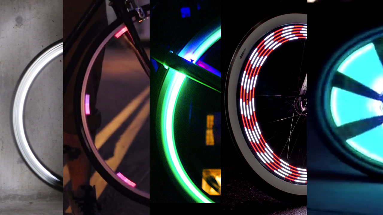
Bike light designs. From left to right: Revolights, Project Aura, Nori Lights, Monkey Lights, Radlicht
I compared them using this chart:
| Design | Revolights | Project Aura | Nori Lights | Monkey Lights | Radlicht |
| Technology | 5mm LED | SMD LED | UV Flourescent | SMD LED | LED/Gas |
| Price (2 wheels) | $200 | — | $60 | $80 | $150 |
| Availability | Today | — | Today | Today | 6 months |
| Brightness/FOV | 9 | 3 | 1 | 7 | 8 |
| Battery Life (hours) | 4 | 6 | 140 | 40 | 5 |
| Animation | yes | no | no | yes | no |
| Selling point: | Arcing headlight | Color POV |
I touted this chart to my IEEE chapter and compared it to a typical parametric chart of voltage regulators from Texas Instruments. There, the criteria would not be not brightness and battery life, but quiescent current and maximum voltage. Note also an engineering theme of tradeoffs between brightness and battery life. LED technology is very bright but only has single-digit battery life. The UV fluorescent Nori Lights are really dim but have very long battery life.
Using the weighted average I described above, I came up with these scores:
| Brightness/FOV | Animation | Battery Life | |
| Revolights | 54 | 30 | 4 |
| Project Aura | 18 | 0 | 6 |
| Nori Lights | 6 | 0 | 10 |
| Monkey Lights | 42 | 30 | 10 |
| Radlicht | 48 | 0 | 5 |
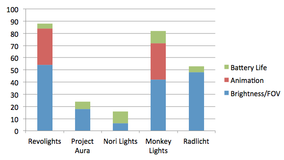
From the chart it is clear that the Revolights design won with the Monkey Lights design coming in at a close second. I chose the Revolights design because you could see it from all angles.
I was ready to buy Revolights, but sticker shock from the price tag stopped me. I thought I could make them for much less. Later I would find out that Revolights are actually “incompatible” with mountain bikes. I also knew that people would approve a lot more if I said I made my own lights.
Design Choices
Microcontroller

LightRider- Revolights sans-microcontroller

LightRider schematic
This was not a project about which microcontroller to use. It was about deciding whether to use a microcontroller at all. Nori Lights and Radlicht do not use microcontrollers. There is also another Revolights clone called LightRider that does not use a microcontroller. This saves significant cost, space, and eliminates all code, saving development time. Very attractive.
I personally wanted an idle animation with dimming. For this reason, I chose to use the Arduino and its six PWM outputs.
On switch
There would be no on switch on this device. I did not want to have to remember to turn on/off two wheels. I would use an interrupt to wake from sleep mode.
Daylight Detection
In daylight, no one notices the lights are on. I decided that the bike lights would only turn on during nighttime. For this I used a photoresistor.
Position Sensor
Now since I wanted the light arc, I needed to know the angular position of the wheel. This is where it got interesting. At first I used an accelerometer. Theoretically it would measure the direction of Earth gravity and that would be angular position. However, when you corrupt this measurement with centripetal acceleration of the wheel and linear acceleration of the whole bike, all changing magnitude and direction in real time, the accelerometer data becomes unusable. Same goes for gyroscopes.
I ended up using a reed switch. They are cheap, simple in code and consume no power. The code measures the period of one revolution and assumes that over the next revolution, speed will not change. Using this approximation, angular position at any instant is calculated and a light arc is drawn.
Battery
For batteries, I used standard Turnigy/Zippy 3S li-po batteries from HobbyKing. I used a 520mAh 3S battery for the front wheel and 460mAh for the red lights on the back wheel since they do not require as much power. The front wheel hub length was 40mm so I had to keep my battery width smaller than that.
I did not realize that the back wheel hub length is shorter than front, so I had to end up zip-tying my back battery the spokes instead of the hub.
Voltage regulator
The voltage regulator I used was the LP2950-33 because it came in a through-hole package and I could order samples from Texas Instruments for free. At 92μA the quiescent current is lower than the regulator on the Arduino Pro Mini, but still not that low, so I would recommend using another regulator. “Through-hole packaging” is also a very bad reason to incorporate a part considering how easy it is to mill a board.
Lights
This was the second most important decision after the mounting hardware. I had to decide both the number of LEDs, LED voltage and LED packaging. There were two options immediately available: 5mm/10mm 3.7V through-hole LEDs or 12V SMD strip LEDs. If I wanted my own custom solution then I could research brand new SMD LEDs with other lenses. I compared with this chart:
| 3.7V Lighting 5mm through-hole | 12V SMD Strip LEDs |
|
|
It was because of the “mechanically simple” and “waterproof” points that I chose to use 12V strip lighting for a first prototype. Theoretically for the same current in both lighting systems, the 12V SMD lights output more power and more light. But honestly, because the 5mm LEDs are so focused, they look brighter. And that’s all that matters in a product like this. So if I were to make a second prototype, I would use 5mm LEDs or SMD LEDs with a lens.
The focused nature of 5mm LEDs is also bad for mountain bikes where the tires are 1.95″ thick. The tires block the light. This is one of the reasons they are “incompatible”

12V SMD Strip LEDs. No lens. Dense.

5mm 3V LEDs with lens. Very bright in a small area.
Mounting Hardware
This is the most important part. Anyone can power on LEDs, but it takes clever mounting hardware to direct the light outward. If I wanted 100 outward-facing lights, rings were the only option.
In choosing a material, I had to consider multiple criteria: how easy it was to work with, weight, aesthetics, and corrosion resistance. I compared two main materials: copper and aluminum. Copper was in the form of 12 AWG wire and aluminum was in the form of bar stock 1/16″ Thick X 1/2″ Width, 6′ Length (McMaster ID 8975K821). A friend of mine also suggested copper piping used for fridge coils, but that was not cheap, didn’t look nice to begin with, not flat and would probably develop a green patina.
I used this chart to compare:
| Copper Wire | Aluminium |
Requires wire stripper and tape |
Requires screws and drill |
They were both pretty viable so I made prototypes with both. For the copper wire, I bent rings with the thickness of 2 wires (about 6mm).
In hindsight, I should have used aluminum for both wheels. And wider aluminum too. The copper wire was a pain to work with because I had to have a circular table of just the right diameter to hammer the copper around and taping it was a pain. The aluminum was a lot lighter than I expected (I neglected to calculate this ahead of time) and it was really easy to work with. Because the 1/16″ aluminum is extremely elastic, you simply bend it into a circle and bolt it together. None of this hammering and sculpting necessary.

Aluminum and copper rings with wire harnesses
The aluminum was wide enough to the point where I could simply zip-tie them to the wheels. The LED strips sit about 3/4″ from the wheel. The copper wire however was so thin that I needed to use spacers to separate them otherwise they would only sit 1/4″ from the wheel. I did not have these spacers, so I imagined them. I had no idea how to bring into real life. My roommate suggested Google Sketchup, so I learned from the “Getting Started” videos in a day and had my models!

Adjustable spacers that separate the LED rings from the wheel. The LED ring sits on top of the left piece and the right piece snaps onto the spoke.
I used my school’s IEEE 3D printer and had my models out within an hour.
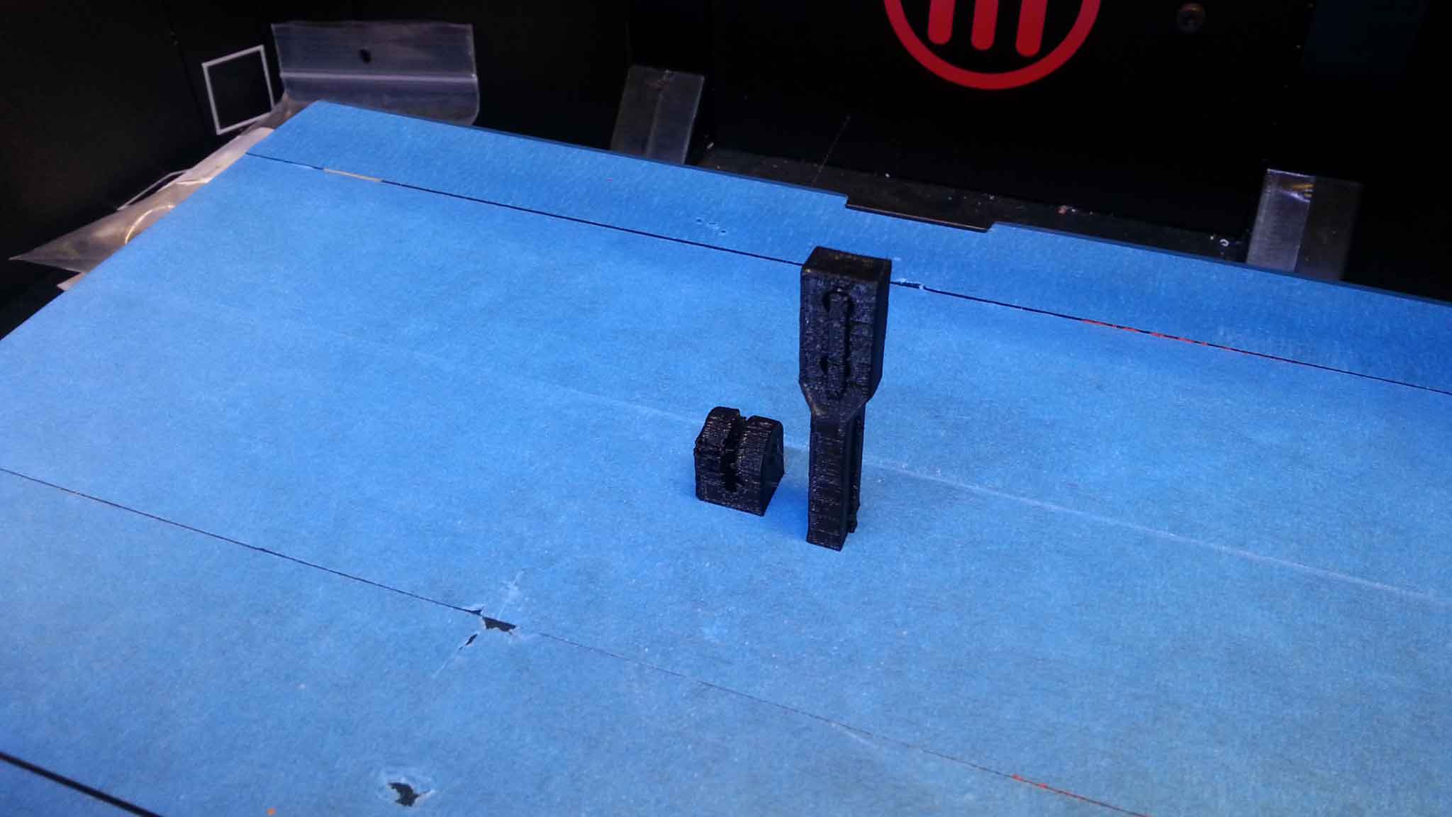
Earlier models freshly printed from the Replicator 2.

The spacer in use with the zip tie securing the LED ring in place
Now as for actually mounting everything to the hub, I simply zip tied everything. I was not very proud of this portion so I never took any photos.
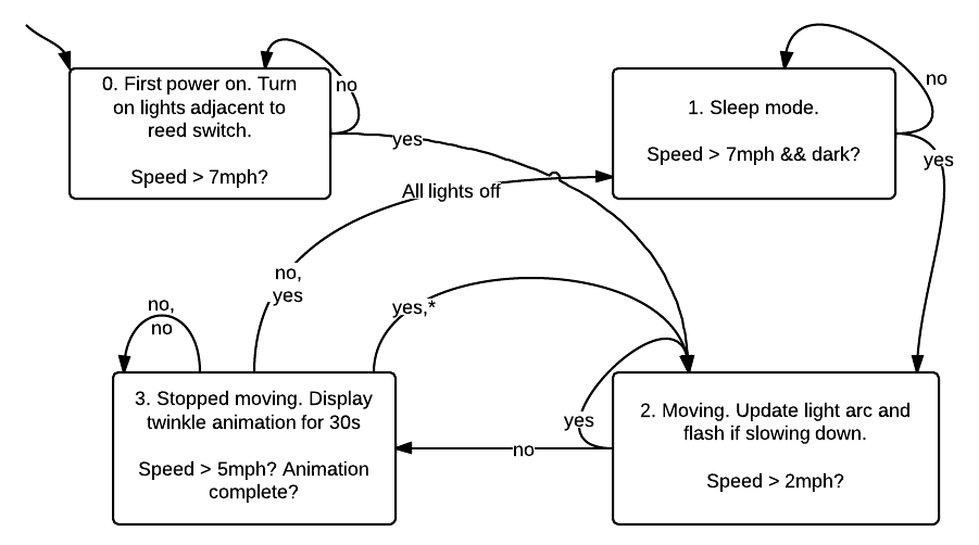
State Machine
Code
I have one Arduino program that works for both wheels. All that has to be done to change from front to back wheel is change the variable BACK_WHEEL to 1. In addition to the obvious feature functionality of the light arc, it also has these features:
- Only turns on at night
- Flashes lights briefly on low battery (voltage-based)
- Enters sleep mode when the wheel stops moving. In my circuit, sleep mode lasts at least 110 days before the battery needs recharging.
https://github.com/androng/SparkleLights
Schematic
The blocks on the right represent my common-cathode LED rings. Also notice that the analog voltage dividers are not connected to GND but rather to an I/O pin that I only turn to GND when measuring. This saves power.

This is the control board I made. Obviously it can be made a lot smaller but it was prototype 2. I later unsoldered the voltage regulator and power LED on the Arduino to save energy in sleep mode.
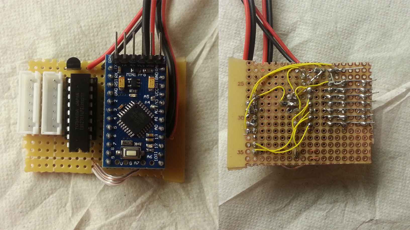
Proto-board control board front and back. JST LED connectors in white, High-side transistor array in middle and Arduino on the right.
I did not want to solder that again so I routed a board in EAGLE and had it milled by my school’s EE shop. It only took an hour! This was remarkable as I am used to waiting two weeks for OSH Park.

Routed board in EAGLE
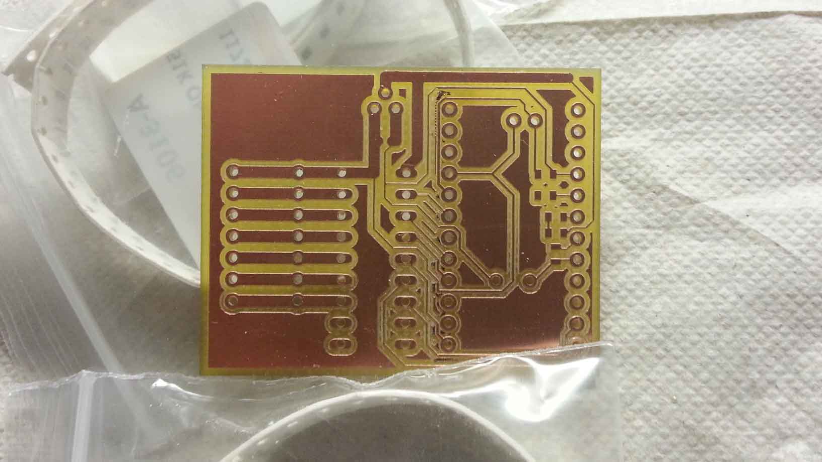
Single-sided board, fresh off the mill
Problems Encountered
This development didn’t go smoothly. There were some big mistakes along the way.
Shorted traces
Boards printed without silkscreen are dangerous. See how the top trace is connected to the thin trace underneath? The top trace is 12V and the one below it is 3.3V. I fried an Arduino here.

Shorted trace at top of board. I witnessed the magic smoke come from my Arduino. This is the autopsy.
Wrong LED polarity
I started assembling my circuit before putting the schematic on paper. What did I find when I put my schematic in the computer?
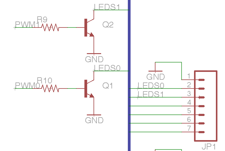
The LED ring is the bar on the right. See how the switching transistors are grounded and the LED ring is common-cathode? Two grounds? No voltage difference? Problem. Because I started assembling the circuit before putting it on paper, I had to switch my transistors to high-side. Fortunately, our wonderful IEEE parts manager was able to supply me with a high-side array.
Metallic Wire-tie
See this wire tie? The entire surface is metallic. I didn’t know this and it did something to my board. I’m guessing 12V touched 3V again. I fried another Arduino this way. Don’t use metallic wire ties.

Metallic wire tie. Bad.
Wrong Layer Milled
Remember the board I milled above? It was wrong. When making a one-layer through-hole board, you need to put the artwork on the bottom. Otherwise you will not be able to solder in headers and sockets. This was the correct way to make the board–with the artwork on bottom, reversed.
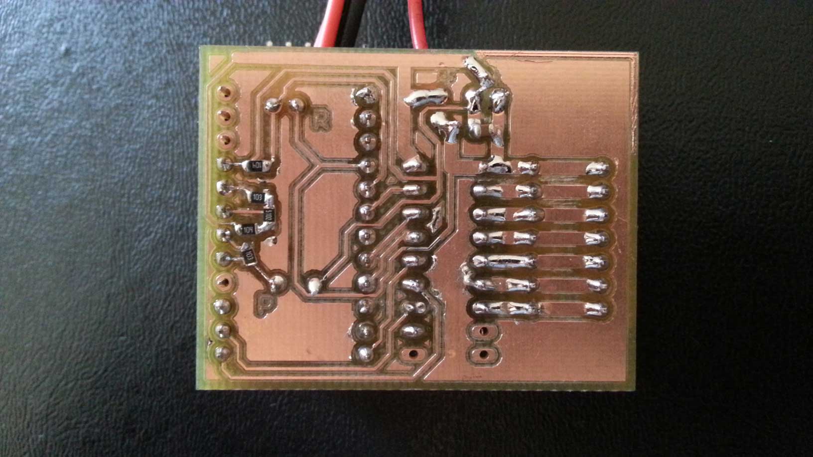
Control board with artwork flipped and soldered. The components are on the other side.
Known Issues
This is the first time I actually have existing issues.
Less than 360° visibility
Despite all my efforts to make wide rings, they still don’t project past the wheel. To me, this is unacceptable, especially for the back because it means now I don’t have a brake signal.
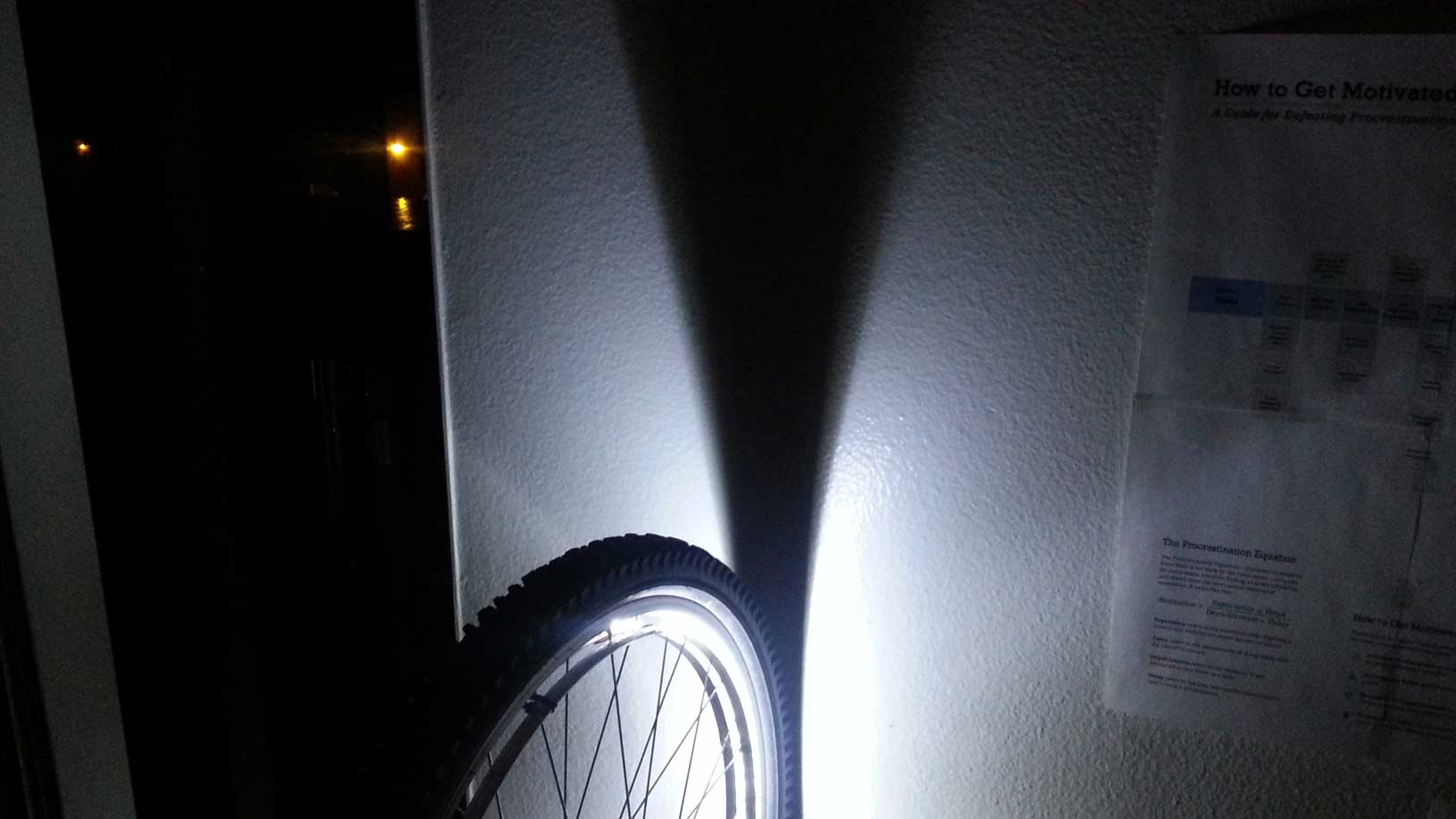
Large shadow cast by aluminium prototype
The only way to fix this is to extend the lights further from the wheel. (wider aluminum)
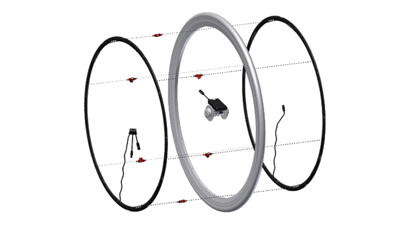
LED rings separated very far from wheel. Image courtesy of Revolights.
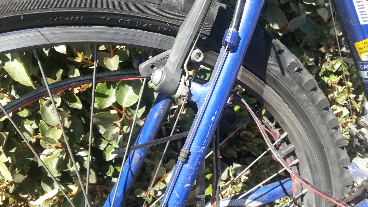
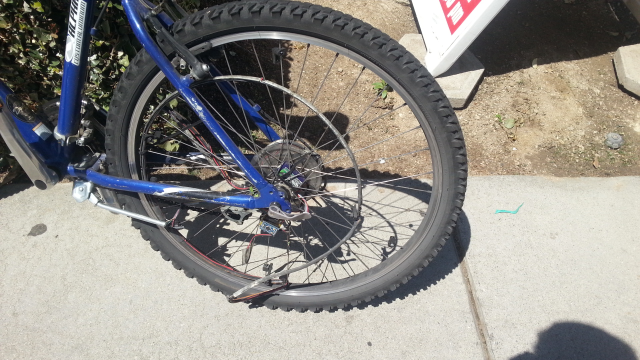
What’s stopping me? The mountain bike brake style. On road bikes, the brake pivot sits above the brake pads. On mountain bikes, the brake pivots sit below the pads.
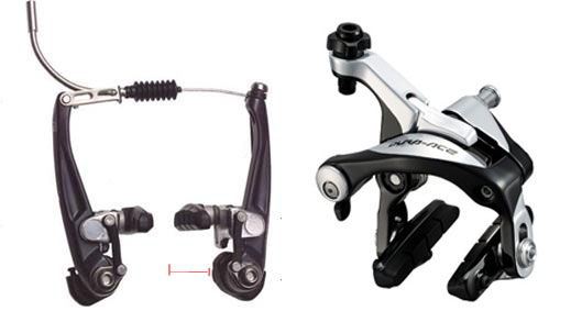
Bike brakes. Left: V-brakes on my bike. Right: Road bike style brakes. Notice the dimension in red that limits my maximum displacement from the wheel. On road bikes this limitation does not exist.
I can either fix this by buying new brakes (unlikely) or making the light ring radius smaller. Making the radius smaller and the aluminum wider would definitely work for the front, but on the back wheel, if the light ring is too wide (1″), the chain can no longer shift to the large gears 1 and 2. I’m OK with that but I definitely wouldn’t sell a product that reduced functionality of my customer’s mountain bike. I am guessing that this is the reason Revolights is selling the “Revolights Arc” instead of an actual mountain bike version of Revolights.
Spoke Mounts
In practice, my spoke mount nuts and machine screws were not screwed tight enough and slid, causing the ring to slide too far from the wheel and produce a clicking sound as the spoke mounts hit the brakes on every revolution. I would have screwed them tighter but the 3D prints simply snapped when I screwed them in too tightly. Also, the 3D printer did not print my hexagonal holes with enough precision. I’m sure that injection molded plastic is more durable and more precise. Until then, I resort to zip ties.
Battery Life
It appears that my battery calculations were off by a very large 50% error. I measured that producing a 180° arc at full brightness takes 98mA. Going by this metric, a 520mAh battery should last 5.3 hours. During my actual discharge test, I measured a battery life of only 2.16 hours. I either set up the experiment wrong, did calculations wrong or both.

False positive start
The lights will sometimes turn on unexpectedly while I am walking with my bike. My state machine tells the lights to only turn on at 7 mph or faster. 7mph is running speed so they should never turn on while I am walking. But they do. I tried adding a “low pass filter”/debounce that doesn’t register the switch if it is actuating faster than 50mph but the problem still exists.
EDIT: 2014-04-16 Catastrophic Wire Catching on Brake Accident
It turns out that my screws on my 3D printed sliders were not tight enough. They slipped laterally and caused the wire harness to get caught in the brake. The entire copper ring assembly was mutilated and I had to rip it all off. What did I learn? Use more secure fasteners like zipties or higher strength 3D prints so that screwing them tight does not shatter them.
The loose wire pulled the brake and caused the wheel to skid
Mutilated copper ring
Future work
- Waterproof. This is my first circuit where waterproofing is a must. I was suggested sugru or hot glue.
- Make the electronics a lot smaller and remove the wire harnesses/bulky connectors.
- Use constant current sinks instead of constant voltage sources
- Blink rear lights when slowing down. Implementing this is harder than I thought because when decelerating, the period of one bike revolution goes up as 1/v where v is velocity. Unfortunately I did not bother because the rear lights cannot be seen from behind [in this prototype] anyway. I would implement this if I had narrower wheels. I would start with something like
-
if(BACK_WHEEL && lastPeriod > secondLastPeriod * 11/10) {}
Conclusion
I achieved about 60% of my technical design objectives. I have great brightness..from the side, an animation, and usable battery life. Unfortunately the limited field-of-view probably means I still have to use a flashlight, but if I forget the flashlight I know that I will still be visible.
One of the things you don’t see too much online is the development process behind products and the previous prototypes. I wanted to document that here. It is very humbling going through this process and realizing that someone else, in this case Kent from Revolights, already went through all these thoughts and his final product is exactly what I wanted, with all the little details solved.
This cost me $80 total with about 30 hours of labor. If I had known this going in and didn’t have to present to my IEEE chapter then I would definitely have just bought Revolights.
Of course, now I get to say that I made them.

Idle Mode – Fading

How can I utilize a concrete resistor in this design?
You can use as a shunt resistor together with an amplifier to create a constant-current output to the LEDs and have much greater control over brightness! Or you can use it to burn a hole through your hand.
What was your source for the specifications used in your comparison chart? I’m curious how you came up with these numbers. Despite the multiple inaccuracies in your depiction of the Nori Lights, I applaud your DIY spirit, and your efforts in sharing the steps you took. Feel free to call me if you ever want to talk wheel lights, or if there is anything that I can do to help. My cell phone number is on our website.
Chris
Nori Lights
I apologize where I was inaccurate. Having never seen Nori Lights in person, I could only guess certain parameters such as “brightness” subjectively from the videos I have seen. For everything else, I tried to use real numbers directly from the website, such as battery life and price. My criteria also played a subjective role in the averages. If I were to prioritize price for example, then Nori Lights would have been one of the better choices.
I have noticed you don’t monetize your blog, don’t waste your traffic, you can earn additional bucks every month because you’ve got hi quality content.
If you want to know how to make extra money, search for: Boorfe’s tips best adsense
alternative