
In this video, I provide a complete tutorial on how to assemble your own stair lighting, featuring block diagram, code overview, testing and final layout. Code and schematic can be found on this page.
Table of Contents
Problem Statement
Design Choices
Microcontroller
Input Device
Output Device
State Machine
Code
Schematic
Assembly
Frequently Asked Questions
Problems Encountered
Potential Improvements
Conclusion
Success Stories
Problem Statement
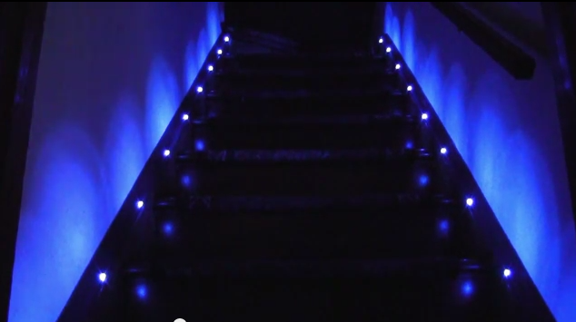
The stairs at night were really dark. It was bad enough that we had to put lights next to it. However, these lights shined in your face and not the stairs. I wanted to light up the actual steps. I really thought the German video was cool, so I aimed for that animation as my goal.
Design Choices
Microcontroller
I chose the ATmega328P firstly because it was on the Arduino. It had the hardware SPI, a ShiftPWM library and good enough speed. If I was mass-producing these, I would probably have chosen a microcontroller with less pins.
Input Device
I had some choices when looking for “person detectors”. I could have used laser sensors, IR beam sensors like they use at the store, or the PIR motion detectors. I initially wanted to use the laser sensors because they show absolute presence vs just motion like the PIR sensors, but they were too finicky. The laser sensors had to be positioned just right on the photodiode, and I didn’t know where to buy the IR beams. The PIR motion detectors actually work very well.
Update 2014-11-09 Since the time of this post there has been a new product in the Adafruit store called a “laser break beam sensor”. If the delay on the motion detectors is completely intolerable then you could try one of these: http://www.adafruit.com/products/2122
Output Device
For output devices, it was clear that I wanted to use the strip LEDs vs the regular point LEDs. I saw some previous implementations like this one and gawked because they didn’t even light up the stairs, only the walls next to the stairs!
This person lit up the wall.
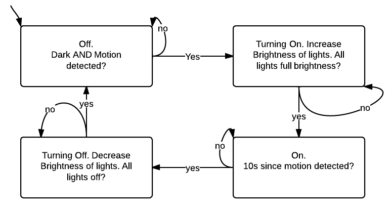
State Machine
Code
Code that runs on the microcontroller may be found on Github: https://github.com/androng/Shift-stairs
Here is a video to help you run the code:
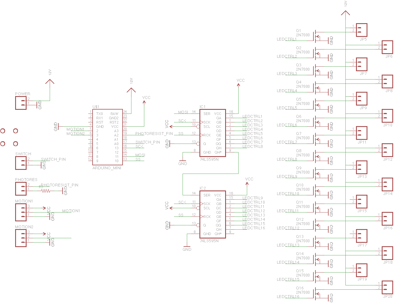
Schematic
I laid out a board but never had it printed. It should be completely functional, but have a look before you print it, especially the minimum distance between traces etc.
EDIT 2014-10-28: I have finally tested the board and it almost works! This was one of my first PCBs and I messed up in my definition of the 2N7000. As a result, you have to solder in the transistors backwards in version 1.0 of the PCB. In version 1.1 this is fixed.
The small rectangle on the left side is a matching through-hole resistor for the photoresistor. I recommend populating the LED headers at the bottom with 2×40 male headers and using black female jumper wires to connect the LEDs. Or you could modify the board to make screw terminals.
Version 1.3: https://oshpark.com/shared_projects/2aD8JaBR
Changes:
1.3
- Fixed “photoresistor always reads zero” problem
1.2
- Added footprint for voltage regulator just in case someone fries the one on the Arduino Pro Mini
1.1
- Fixed backwards transistor problem
- Added more labels for power, motion detectors
- Added labels for MOSFET source, gate and drain just in case you want to use a different MOSFET.


PCB with connectors. I originally wanted to use the red connectors but I didn’t realize they were too thick, so now I recommend the black connectors on the right side.
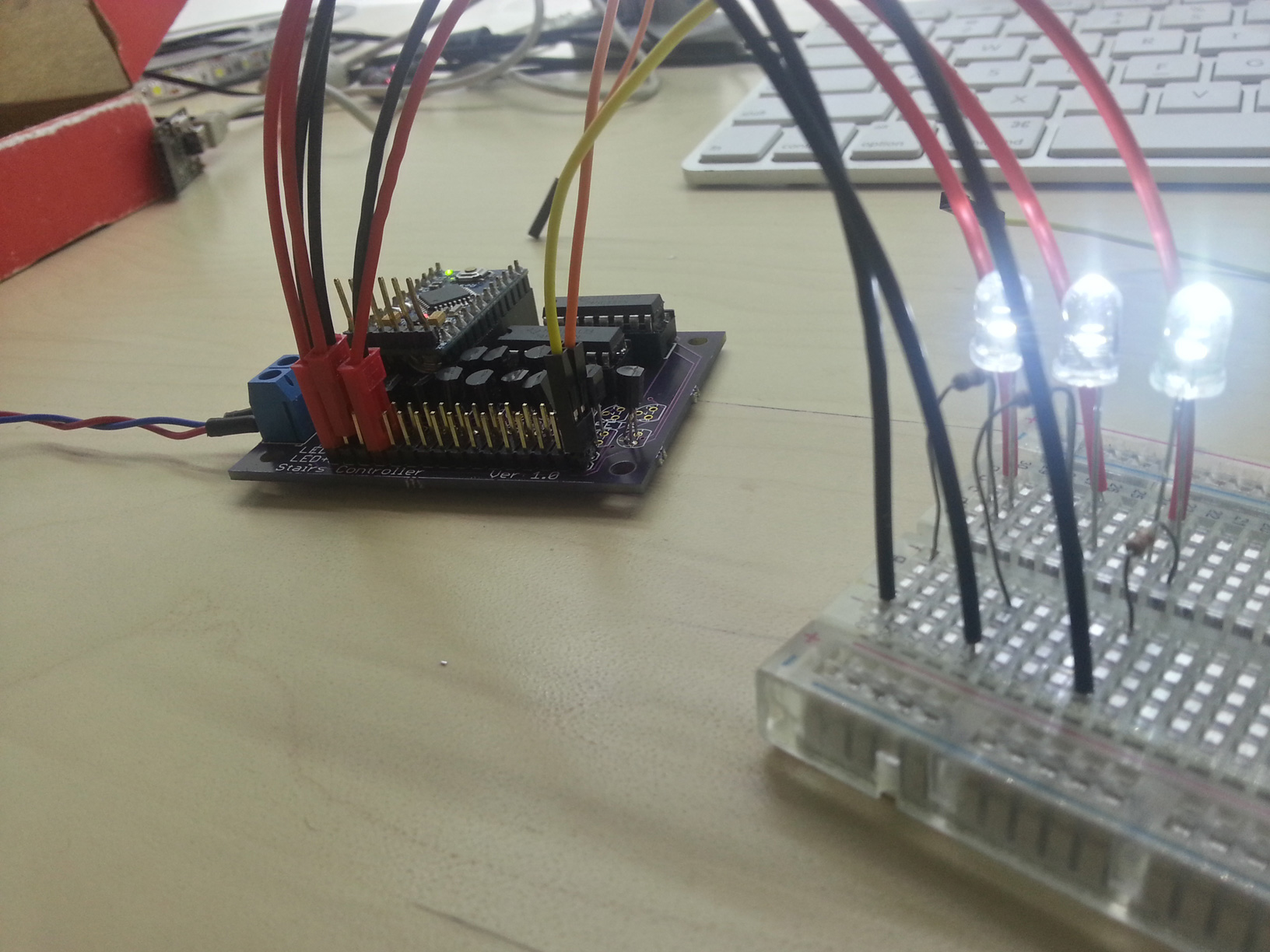
When you solder everything correctly, this should happen:
Assembly
You will need:
1x Arduino Pro Mini 5V, find on eBay
5m 3528 white LED strip, find on eBay
1x 12V 3A Power supply, find on eBay
PCB, $30 from OSH Park, see Schematic section for link
Enough wire for your stairs, you can also buy similar from Home Depot
2x PIR sensor or Laser sensor
PCB parts:
20x 2N7000 MOSFET or any other pin-compatible MOSFET. SOT-23 packages work well on the PCB too.
1x Single row female header
1x Double row male pin header
1x Single row male pin header
1x (Photoresistor and 10k resistor) (optional)
1x Switch (optional)
1x Screw terminal
2x 16-pin socket
2x 74HC595 Shift register
1x (LM7805 regulator and 0.1uF capacitors) (mandatory)
20x Female Jumper wires (one item comes with several wires)
Tools:
1x USB-to-UART
Soldering iron
Heatshrink and lighter – use the smallest size and cut into 3 pieces each
Wire stripper
Screwdriver
I recommend buying 2 or 3x everything in the “PCB parts” section in case you decide to start over.
Instructions
Assembly video and more detailed instructions coming in the future when I have time
- Assemble Arduino Pro Mini–solder male headers below on the long sides and above on the short sides
- Set jumper on USB-to-UART to 5V
- Connect USB cable > USB-to-UART > Arduino Pro Mini and program it with Blink sketch
- Assemble PCB (refer to photo in PCB section)
- Solder female headers in the “Arduino Pro Mini” slot
- Solder LED+ and LED- with double row male headers
- Solder side pins like “motion” “switch” etc with male headers
- Solder in sockets for shift registers and insert the shift registers
- Insert Arduino Pro Mini with FTDI header in the middle of the PCB
- (optional) Solder in regulator and capacitors
- Assemble LEDs
- Cut a female jumper wire in half
- Put heatshrink on the half-jumpers
- Solder half-jumpers to a 2-conductor wire, then solder 2 conductor wire to LED.
- Connect your jumpers to the PCB male headers
- Repeat step 5 for however many stairs you have
Frequently Asked Questions
How do I adjust the number of steps? Only nine of the steps turn on.
One of my lights doesn’t turn on/off or it flickers.
My lights stay on and never turn off.
One of my motion detectors does not trigger or has many false positives.
Problems Encountered
My choice of female headers as connectors for the LEDs was really bad. The headers are very secure, however all the wires are exposed and it is hard to place one in the middle. Other than that and the point-to-point soldering, I really did not have any problems.
Potential Improvements
Like stated in the video, I would have improved these things:
- Use constant-current LED drivers
- Add second override switch
- Feature: first step always on at night
- Route PCB with FTDI, ISP or Arduino socket on it.
- Made duty cycle vary exponentially with brightness to cancel out the logarithmic perception of brightness. I almost did this, but the effect was not noticable enough for me to spend a lot of time on it. I left it in the code as a large array. (it should be placed in program memory)
Conclusion
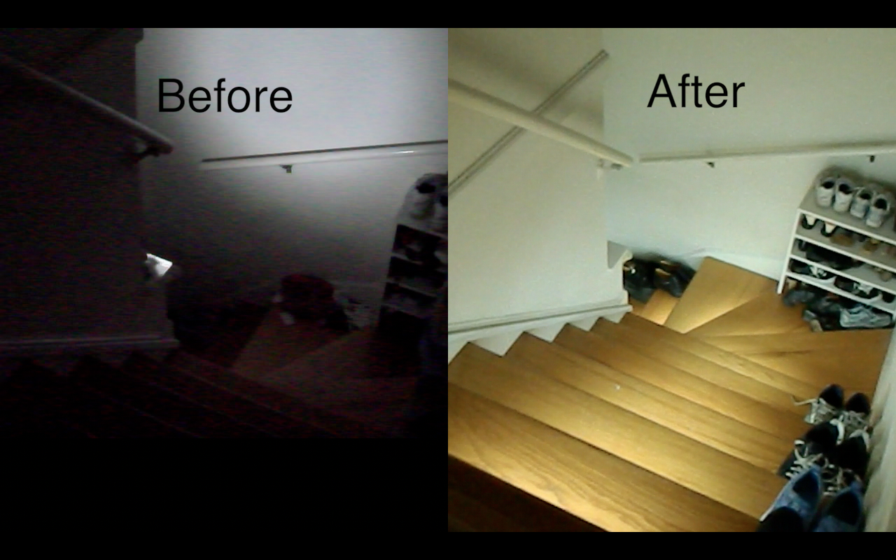
I accomplished the objective of lighting up the stairs as well as adding some extra features like daylight detection. After a long time, I finally completed the documentation and edited together the film I captured so long ago! I feel accomplished.
Success Stories
People like you and me have succeeded in banishing the darkness! Publish a video to YouTube, link to it in the comments, and I will showcase it here. Include a link to this page in your video.
Boštjan Perme 2017-02-27
Joshua Mauldin 2016-10-16
troysbucket 2014-11-25:

msvetec 2015-10-04

SG 2015-12-01

Gökhan ÜNAL 2021-07-05

Hi Andrew,
thanks for designing and programming this awesome unit.
Ive build two but had some issues with the PIR’s (due to the environment)
Ive tried to solve this with other sensors GP2Y0A21YK0F
the Work awesome but just up to 25 centimeters
The problem lies in that the analog voltage out will range from 3V when an object is only 4″ (10 cm) away and 0.4V when the object is 32″ (80 cm) away.
Unfortunately the Arduino has High on its input only when 3v is send to it.
https://www.arduino.cc/en/Reference/Constants
Im trying to read the code, and can read some of it, but i have no arduino experience and its and couldn’t quiet get it unfortunately.
Could you spare me some thoughts?
thx
Thijs
Hey Andrew. What do you think, is it possible to use these laser switches to trigger the lights:
http://www.ebay.co.uk/itm/Infrared-Laser-Alarm-Switch-Sound-Light-Alarm-Motion-Senser-Security-Diy-Kits-/131574426031?hash=item1ea27269af:g:kHsAAOSwNSxVJNks
My stairs lights are working well but there are still issues where sometimes they wont trigger to movement and sometimes they trigger themself. So i’m in search of better triggering system.
Thank you!
Yes it is possible. If you know how to wire up the photoresistor such that it produces a high/low for the microcontroller and you run a wire to the other side of the stairs for the laser then it will work.
My PIRs work fine if I angle them downward. No false triggers and they trigger every time.
Would it be possible for you to contact me through email….? I am getting the Brightness not declared in this scope error. I have read EVERY comment and your answers just to familiarize myself with ALL the issues identified with different experimenters and tried all the suggested remedies for this issue with no luck. From my conjecture, it seems the Arduino IDE is looking for a “brightnessSM.h” file for a library, but I have none in the unzipped collection of files. Is it possible that the “brightnessSM.ino” has to be pasted into the Stairs_Shift.ino and declared as an .ino?
Thnx, Danny
Are you using Arduino 1.5.8? brightnessSM.ino should be the second tab open.
Yes….I opened everything that was showing in your screenshot and it finished compiling without error. Having that brightness.ino open while attempting to compile wasn’t mention in the workflow. If it was…I must have missed it. Working with known to unknown approach, I had the suspicion that the compiler was looking for code from that .ino
Thanx for the reply….now I just have to build the board.
Stay tuned….I know about as much about Arduino as I do brain surgery, so this may turn out to be a painful experience.
P.S. I’m sure it will be worth the pain…your project looks so cool it ain’t funny!! Additionally, it appears looking at the schematics that is can be tweaked to add quite a few other options as well.
Just to clarify….the board you have designed appears to accommodate up to 16 steps or channels. Is editing Line#22 to express the exact number of channels desired the only thing that needs to be done to utilize all 16?
Thnx again, Danny
Yes
One last question for the time being until I get the board built and the Pro Mini ready to program……
Is it possible to adjust + and – the time between when the first LED comes on/off and the successive ones after that? Looked thru the code and can’t discern where the timing is specified.
Thnx, Danny
Yes it’s possible, but not by adjusting one variable. I did not have adjustment in mind when I coded it. I’m working on a new version that allows it to be changed but it’s not ready yet.
Mr. Andrew…Would it be possible to update the color image of the circuit board on this web page that illustrates the top and bottom traces in red and blue to Ver: 1.3?
When I print the Eagle prints, the silkscreen obscures the traces that include the 7805 and caps that are on the project image site where the newer board file is downloadable. Or define point to point connections where the regulator and caps are incorporated into the existing color image or even a pencil line drawing of the addition to the 1.1 schematic?
Sorry to pester…at work stoppage at this point until clarified.
Thnx, Danny
Hi Andrew. I designed your PCB board accommodate my needs, but I have one problem though which is 1.3v you mentioned that voltage regulator and cap is mandatory. So I could not find it on your schematics. Can you able to share your 1.3 version schematics?
That would be huge help.
Thank you in advance.
The 1.3 schematic is the same as all the others. It was only PCB layout problems that were fixed.
Actually I see what you mean. I’ll put up the updated schematic image with the regulator.
I made one and like this project…
Would you like to make a video with the PCB and your lit stairs to show off?
I see. Well, is it worth building the project the way it is currently or will the “new & improved” be coming out soon enough to be worth waiting for instead?
And…how did you learn your coding skills?
The new version will come out in maybe a month and cost a lot more but it will be targeted toward people who don’t want to solder. I would just make it now and replace the code that adjusts the brightness. You’ll like it more.
I learned from my high school teacher! =)
Well…I must say…it is quite a gift….I am just beginning to dabble in it. Would also like to be able to do PIC programming as well. However, for an old fart like me…the learning curve seem overwhelming.
This is a nice and friendly beginner project to introduce you to the world of Arduino. Props for learning at “old fart” age. My parents dont learn anything new anymore.
On Mon, Feb 26, 2018 at 6:34 PM, Speedy Signals wrote:
>
Just curious…what other projects have you published? I’ve looked through all your archives and didn’t see anything on par with this stair light project.
Did you check out the Electronic door lock project? It has a video too. To be honest I haven’t published much more because it takes weeks to make a video and I’m not sure what projects people want to see.
On Mon, Feb 26, 2018 at 8:32 PM, Speedy Signals wrote:
>
Any update as to when new “Brightness” Library will be downloadable….? Got most of components together…just waiting on the PIR modules and the Pro minis to have all.
Thnx, Danny
Direct: danielgraham1961@att.net
It won’t happen any time soon. Try writing it yourself. That’s one purpose of this project. To help you understand basic timing code.
On Thu, Mar 15, 2018 at 10:36 PM, Speedy Signals wrote:
>
I like your lighting system and i just want to build one too
Can you please tel me what Arduino pro mini version should i buy and do you have any new PCB board design or i can use the V1.3
Thanks in advance …
Buy a 16MHz 5V Arduino pro mini. I have a newer PCB, v7.0, but it costs about $100 and it is fully assembled instead of the current v1.3 board that you have to buy and assemble yourself. The new PCB has no documentation yet and is not online, and it only works with 16 steps max. If you are interested, I can produce more documentation and ship you one for $100 and you can be an early access user. Or you can just order v1.3, which several people have used at this point.
Thanks your feed back but i need 20 steps other wise it not nice with my staircase. Can I modify your PCB with extra 74HC595 Shift register and increase the steps count ? Is it possible?
It is possible but you will also need 4 more MOSFETs to go with the shift resisters. See the schematic for how to chain them.
One more i have 20 steps in diagram it show only 16 led . can i extend it easily to 20 steps
is it same as PCB board design
It’s not very easy to extend it to 20 steps. You’d have to edit the EAGLE file and fabricate a new PCB with OSH Park. The existing PCB will not work.
Pingback: Stairs Lights Kit is ready to be commercialized! | Speedy Signals
Hi,
is it possible to use a Pro Micro atmega 32U4 board instead of pro mini?
Yes
Hi Andrew, I have tried to load the code to Pro Micro, but I constantly get an error. Even when I try to compile the code with Leonardo (bootloader for micro) I get an error that it is not compatible with this board. I have checked the bootloader on the board and everything is OK. Do you have any idea what could be wrong. Is there some changes that needs to be changed in the code itself?
Hello Andrew
After a year of good lighting of my stairs, the lights are constantly lit.
I replaced the motion detectors because I thought a false positive but it did not change anything
I also changed the arduino the result is the same.
You or the community would have a track to solve this dysfunction?
thank you in advance
Fred
If you unplug and plug in the circuit, does it fade on and off? If so then the main circuit still works and there is a peripheral malfunction. It could be the override switch. Did you plug those in?
Hi Andrew, sorry for the time of response but my lighting system of my stairs is given to it works alone. I preferred to test a few days before drawing conclusions. yet it did not work for several days before I did tests and I contacted. I do not complain it works 😉 thank you again you were really the person who allowed me to make this staircase !! Thank you !
Hi Andrew, hope you’re still following this thread and are well. Due to the current pandemic, I decided to continue with this project after buying the boards back in 2015. Ive almost finished now and will be posting the results. Can I ask, after setting the new light level by adding the serial command in the loop() section, is it wise to remove the line, in other words, clean up the code before commissioning the project. Regards
Yes, it is wise to remove any unnecessary code before using the project.
Hi Andrew, hope you’re still following this thread and are well. I want to complete this project since i left. so,when i tried to compile this code it shows brightnessSM not declared.how i rectify this error.I am using arduino ide version 1.8.10 and also i want to complete for 23 stairs so i have to just edit line no 22 and increase the circuit diagram…..?
Use Arduino 1.5.8. Arduino 1.8 does not compile the code correctly.
thanks for the reply and one more thing i have to make for 23 steps so what i have to change in the code.
Change this line to the number of steps you have https://github.com/androng/Shift-stairs/blob/master/Shift_Stairs.ino#L22
thanks once again and last question do i have to increase no of 74hc595 ic in order to increase steps and what is registers in code do i have to change also…? if i am not wrong here registers refers to no of 74hc595 ic used in circuit.
You can see in the schematic https://speedysignals.com/2013/08/01/how-to-assemble-stair-lights/#Schematic that to connect another register, you have to connect pin 9 of the first register to pin 14 of the second register, and pin 9 of the second register to pin 14 of the third (new) register
Ive finally got this up and running and it works brilliantly.
Very nice. Your setup looks very clean.
Hi Andrew , i like your project very much , i all ready have a led controller but yours is more compact then mine. I orderd the pcb and all the parts , i solder the parts on the pcb and programmed the arduino mini. All went well but , i turn the power on and the led’s start with flikker ing and then burn constant. What did i do wrong ? I used V1.3 pcb , i made no changes in the file. Can you help with this ? O perhaps someone who made it with succes.
Hi Jan. The LEDs will stay on if the “SWITCH” contacts on the PCB are connected. Try removing any complement you have soldered there
Wow thanks for the fast reply , i did not now if it whas still active.
I have checked the board but cant find a bad spot , i will remove the parts of this pcb ( i have 10 pcb’s ha ha ) and solder a new one. If it does the same i come back with pictures. I assume i dont have to change anything in the sketch if i use it for 8 stairs ?
Best wishes to all and a corona free 2021.
The PCB will work without anything soldered to the “SWITCH” contacts. Try turning it on without anything there. And share a video of the behavior because I’m not sure what “flickering” means.
What i mean with flickering is , when i power up the board the led’s go on and off realy fast and then they just stay on.
A close up picture of the front and back of the finished board might help to start with.
The pir sensor will keep the lights on as long as it sees you. Try moving away from the sensors and wait for a while, if there is no problem, the leds will turn off.
Hello Andrew; After a long time, I finished the work. Video here
I would appreciate if you put this video in the successful stories section.
Hi! I am attempting this project and each step is taking me a long time as I am a true novice. Anyway, when powering up the printed circuit board, the transistors caught fire. Should I get a voltage reader and confirm the electrical output? I’m wondering if the voltage is higher than advertised for the lights I purchased. Any other suggestions? Thanks
Hi! I love your tutorial. I had a question. The first attempt to power the circuit, a transistor caught flame. Do you have any recommendations? Has anyone used a fireproof project box? Should I verify that my volt output is as advertised on the product labels for the LED strips I purchased with a voltage meter? Thanks for reviewing?
If the transistors caught fire then you may be using them above their maximum current limit. Or you inserted them backwards. or both. Make sure the source and drain are inserted correctly. I put little S and D on the circuit board for that purpose. Take a photo with the transistor part number showing and I’ll verify it.
We have another issue. We removed the transistors, and yet the lights still turn on. Did we create a short? Before removing the transistor, we tried using a new transistor in the alternative direction (reversal), and then the lights never went off. Initially, We followed the schematic diagram to determine order for the transistor. The transistor has a round side and a flat side. Should it be aligned with the rounded sides on the circuit board, or is it reverse? Thank you for your review.
https://healthgeographer.wordpress.com/2023/03/17/arduino-progress/