My stairs lights PCB is ready to be commercialized! Hooray, a product!
If over 100 people order, I could offer the PCB by itself for $100. Otherwise the price will increase. I can also offer full kits with everything (motion detectors, LEDs, case, wires) included for $300. Leave a comment if you are interested.
Story
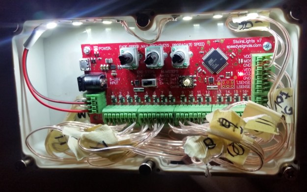
I have a few posts on this blog and the “stairs lights” post is by far the most popular. Because of this, I completely remade the PCB from scratch using parts from Digi-Key and replaced all the through-hole parts with surface-mount parts. I kept the Arduino bootloader, but no longer require the user to program the PCB. Adjusting settings is as simple as turning some knobs.
The product is still in validation stage and I welcome feedback. For example, is it tolerable to run 16 pairs of wires down the stairs? Are the settings I chose to adjust actually useful? Would this board be useful somewhere else besides stairs? What kind of case would you like? Is installation still too hard?
Demo
- Intended for use with 12V LEDs (board can support 24V upon request)
- Features on-board test LEDs to validate settings before running wires
- No programming required
- Push-down wire terminals eliminate need to solder terminators each step’s wires
- Adjust fade speed, max brightness and propagate speed with knobs
- Adjust number of steps with knob
- Optional mode to keep top and bottom steps dimly lit all the time
- Attach two optional switches to keep lights on indefinitely
- Attach an optional photoresistor to disable the lights in daytime
Assembly
This assembly was done with my mini stairs.
Technical specifications
- Supports 1-16 steps
- Stays on for 20s
- Input voltage: 5-16V (can go up to 28V but it’s more expensive and I don’t think anyone wants this)
- Animation can be triggered every 25-200 seconds
- Microcontroller: ATMega32u4
- 8-bit, 75Hz PWM
- Power usage of the PCB by itself with 12V supply: 0.8W
- Works with 12V active-low pulldown motion detectors
- Max current per step: 2A
- Max total current through VDD and GND terminals: 4A (assuming using two conductors for VDD and two for GND)
- Wire terminals accept 20-26 AWG (0.2-0.5mm^2)
FAQ
Can I just use one LED strip and two motion detectors?
Can I adjust how long the lights stay on before turning off?
No. I kept this at a fixed 20s. If enough people ask for it, I can replace the “propagate speed” knob to adjust “on time” instead.
Do I still need to solder?
Is it made in the US?
Is it open source?
Not yet.

Cool!
Did you ever get the code updated?
At one point I thought you had told me you were in process of doing so.
Thnx, Danny
Yes, the code is updated, but it’s made for PCB version 7. https://github.com/androng/Shift-stairs/tree/Positive_logic With some adjustment, it can be made to work with v1.4. I don’t have the v1.4 hardware anymore though so it would be difficult for me to work it out.
Hi. Are you able to sent to the UK? Thanks.
I am not shipping anywhere because I have not observed any interest
Hey Andrew, looks good, do you have an email address I can communicate directly from?
Hi, very nicely done, it would be possible to publish PCB ver.7 schema please.
Thank you.
Hello Andrew!
I haven’t been on you projects site in quite a while. The last I heard, you were going to make a few modifications and add other features to your stair lighting project and then possibly produce the end project commercially.
Did that ever happen?
If so, what kind of pricing do you have on a plug and play modular board ? The lights, wire enclosure and other hardware I can gather locally if I don’t already have it in my extensive “PROJECT” stockpile of junk.
Thnx, Danny
Hello Danny. I never commercialized the stairs lights board. I assumed that a price of $400 that I was going to charge for an all-inclusive kit was too high and that the instructions were too complicated and labor-intensive. e.g. “Step 10: solder 12 pairs of wires to LEDs, Step 11, label each individual wire with a number” I did not know how to find customers either. I said that I would redesign the lights to be a lot simpler and cheaper, but I haven’t done it yet.
If you want, I can send you the PCB in the picture along with the schematic for $99.(No case or other hardware included)
Will the PCB be “Plug and Play” with the additional hardware I provide, i.e.: micro controller already programmed, etc, etc? Also, could I pick your brain over time to make adjustments to the code to tailor the application to the # of steps, delay timing, and any other variables that may present in a final installment and application?(NOTE: I took a job with the railroad that had me on the road 26 days a month and that resulted in an abrupt halt to any progression of my endeavor to self educate in the arena of coding and programming.) I have just gotten to a point that I can start blowing the dust off of my stockpile of parts and unfinished projects/experiments.
Thnx, Danny
The microcontroller on this board is already programmed and can be adjusted using knobs as you can see in the video above. Editing source code is not necessary
Awesome!
I will be getting back to you on the PCB later on after I get the other hardware installed on the stairs. Do you have a recommendation on the dimensions of an enclosure?
Thnx, D
hi can you send me the circuit diagram at my mail address alakh.madhav32@gmil.com for this updated version that you made.
I Just read your post, it’s very informative and helpful too for readers. Dark spots and shadows may cause safety risks. Lighting in the courtyard is extremely important in terms of safety. led flood lights of best quality enhanced the appearance, safety and security of my garden and courtyard..