In this video, I show how I solved my hourly hydration problem by wiring a transistor to a water pump behind my desk. I describe three different ways of switching: MOSFETs, BJTs and relays. I then skim over logic gates and show how I added lighting to my bedroom.
Music from http://goo.gl/NblLp
Video overview
This overview is meant as a complement to the video. I will try not to repeat information, but I will restate the problem and provide links to all the simulations. I will also add things that I did not have a chance to include in the video. Make sure to read the Transistor selection process section.
The Problem
Transistors to the rescue!
You can switch LEDs too
Logic Gates
More information
Transistor selection process
What could have been done better
The Problem
I like to keep hydrated. I don’t like to distract myself by standing up six times a day for a task that was just begging to be automated. I bought myself one of these for instant gratification: [www.terapump.net]. Unfortunately it was unsightly and the switch required way too much force to operate.
Transistors to the rescue!
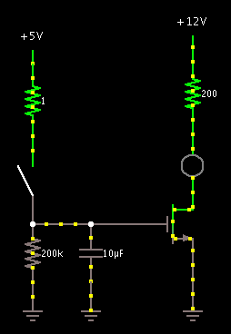
I wanted to use a small switch to control the pump, so I connected three different types of switches: a MOSFET, a BJT (bipolar junction transistor) and a relay. The first two simply did not do anything when I applied a voltage/current. The relay was supposed to click on, but instead continuously turned on and off, producing that interesting sound at 1:11. I should have used a relay with a lower coil current, but I did not have one on hand.
To see the simulations, go to falstad.com/circuit/ and download the JAR. Open it and import these text files:
 MOSFET |
 BJT |
 Relay |
I wanted to see if the relay’s time-domain waveform looked special at all, so I took the audio from the clip and viewed the samples in Audacity:
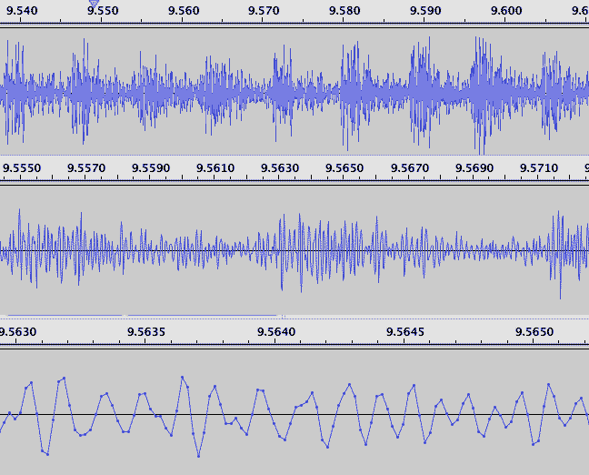 The time domain waveform didn’t look very special, but it certainly sounded interesting. I was expecting something more square. |
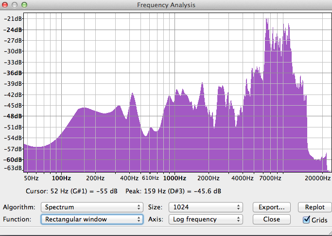 The spectrum shows a lot of high frequency content. This matched the foreign sounds of the video. I bet there was more that the microphone didn’t pick up. |
When the relay is being connected in the video, you can see the large voltage drop on the meter to 3.27V. In fact it worked this way with all of the switches. The power supply could not turn on the switch and provide the large startup current for the motor. When I switched the power supply, it actually maintained a voltage of 4.5V, enough to turn things on.
There was something else I was not able to explain: When I turn the pump on at 1:33, the LED turns on. I know that turning the pump off creates the inductive voltage, but I thought turning it on would make current move in the other direction and not light the LED.
You can switch LEDs too
The rest of the video goes into switching LEDs assuming the correct MOSFET was chosen. In the video, some basic circuits are shown. If you want to be fancy, you can create a dim in or out effect with a microcontroller and PWM a capacitor.
This circuit will slowly turn off when the switch opens by discharging a capacitor. The key is to choose the supply voltage on the left to be only about 2-3 times the threshold voltage of the MOSFET.
Logic Gates
The video shows many AND and OR configurations made from switches, diodes and transistors. It shows that they scale infinitely (n-inputs).

OR Gates. Ignore the zero ohm resistor. The simulator does not allow a wire loop with no resistance.

AND Gates
What I did not get to show in the video was the switch-based n-input XOR. It uses DPDT switches:

Four-input switch-based XOR.
The diode based XOR is a little complicated. One design I have seen is on CircuitLab: https://www.circuitlab.com/circuit/q5y7c5/xor-using-diodes/

XOR using only diodes and one transistor.
One transistor-based based XOR can be found here: http://www.falstad.com/circuit/e-cmosxor.html
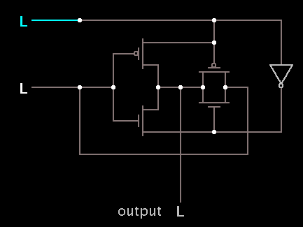
CMOS XOR
More information
Original pump wiring
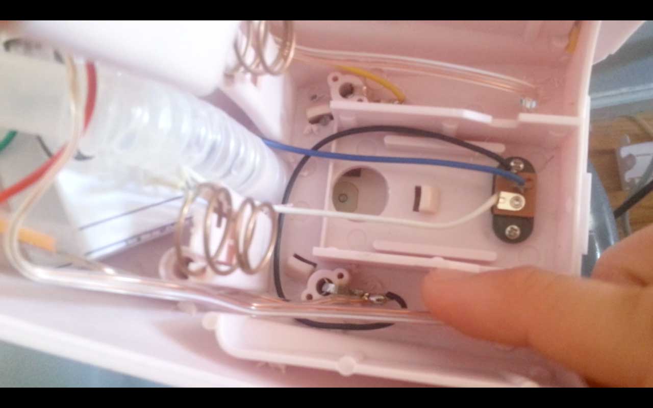
Wires in water pump. The blue and white wires go to the battery terminals ad the black wire goes to the motor+. The yellow wire is motor-. Ignore the clear wires–those were added by me.
This is the wiring diagram that I created from the colored wires:
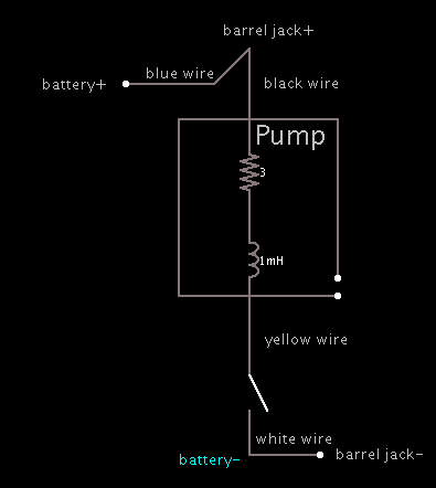
Blue and black are the same point. Don’t put batteries and the AC adapter in at the same time.
This led itself naturally to a transistor low-side switch.
Transistor selection process
How do I select a MOSFET?
The design process for a low-frequency switching MOSFET is not difficult. First, you should know how much current you need. For a motor, the most current you need is the initial starting current. For an LED and resistor you can measure this directly–it never changes. This value is called your “drain current” ID.
Once you know ID, you may then select a MOSFET from whatever website catalog you choose. The wrong way to do it is to simply say “I need to switch 3A, so I’ll multiply it by 3 and select only MOSFETs with 9A or above!” The maximum drain current is limited by the power dissipation and will likely be lower than advertised: http://mcmanis.com/chuck/robotics/projects/esc2/FET-power.html
Ok, so you have done the power calculations and narrowed it down to a few MOSFETs. How do you predict whether your circuit will turn on or not? First we have to understand how a switching MOSFET works. When a MOSFET is on, it has two modes: triode/linear and saturation. Taking a figure from Sedra Smith’s Microelectronic Circuits 6th ed:
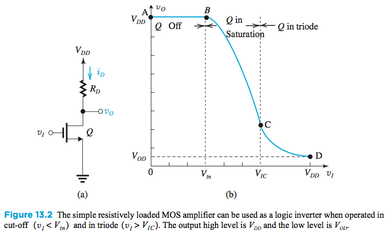
You want to operate in the triode region because it means less power dissipated in the MOSFET and more delivered to the load RD. To predict the drain current, you need to determine the threshold voltage Vth and the MOSFET transconductance parameter 

Drain current vs Vds curve
Threshold Voltage
I picked an arbitrary point in the saturation region and read these values: VGS = 5V, VDS = 6V, and ID = 4.5A. I also picked a threshold voltage of 3.0V from the range in the datasheet even though it says ID = 250μA. Higher ID will cause a lower Vt, so if anything, the MOSFET might work better than expected (with limits). With all these values, you may now plug into the saturation equation and solve for kn:
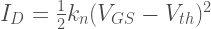
kn = 2.25
Now let’s pick a sample circuit and predict the voltages and currents before we buy the transistor! I chose this circuit:
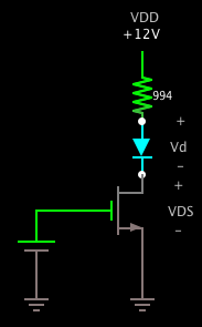
MOSFET Switching LED
The i-v relationship for the resistor is just Ohm’s Law: V = IR.
The diode I used was the white LED from the video at 1:40. It’s i-v relationship is dictated by the Shockley diode equation:

Where do we find the constant Is? We take a data point and solve for it. In my case the diode conducted 2.585513 mA at 2.84V across it, so using VT = 25mV, I obtained Is = 1.19060187e-52. Now we have an i-v relationship for the diode.
For the MOSFET we have to assume it is operating in the triode region to solve this problem. Then after we are done, we check to see whether the triode condition is satisfied and if not, solve assuming operation in the saturation region. The i-v relationship for the MOSFET in triode is:

We solved for kn and VGS is a constant. Now we write an equation for the voltages:

and we have three equations with three unknowns! Time to write a MATLAB script to solve! I used my TI-89 at first but it seemed to hang on the solve command.
% MATLAB R2012a
% Simulation for this circuit: http://goo.gl/4ChMc

clear all
close all
clc

% Drift current I_s (constant for a given diode at given temp)
s = 1.19060187e-52;
% MOSFET transconductance parameter k_n=(μ_n)(C_ox)(W/L)
k = 2.25;

% Threshold voltage of MOSFET
vt = 3;
% Gate Source voltage
vgs = 5;
% Supply voltage VDD
vdd = 12;
% Resistance R
r = 994;

% Solve assuming triode region
syms i vd vds
[i vd vds] = solve(i == s * (exp(vd/.025) - 1), vds == vdd - i*r - vd, i==k*((vgs-vt)*vds - 1/2*vds^2), i, vd, vds);

% Confirm triode region
vgd = vgs - vds ;
if vgs < vt     disp('Cutoff (VGS > VT)');
elseif vgd > vt
    disp('Triode region (VGD > VT)');
    i
    vd
    vds
    vgd
else
    disp('Saturation (VGD < VT)');

    % Solve again with saturation equation
    clear i vd vds
    syms i vd vds
    [i vd vds] = solve(i == s * (exp(vd/.025) - 1), vds == vdd - i*r - vd, i==1/2* k*((vgs-vt)^2), i, vd, vds);
    vgd = vgs - vds ;
    disp(['i: ', num2str(double(i))]);
    disp(['vd: ', num2str(double(vd))]);
    disp(['vds: ', num2str(double(vds))]);
    disp(['vgd: ', num2str(double(vgd))]);
end
Here is the output:
Triode region (VGD > VT)

i =

0.009181312020793884304169679364481

vd =

2.8717345180102711269280110506458

vds =

0.0020413333206078747273276610601233

vgd =

4.9979586666793921252726723389399
These are very reasonable values. The predicted current is about 9.18131mA, the LED voltage is 2.9116V, and VDS is very low. I actually went and connected this circuit and found that my value for LED voltage was +6% off and my value for current was -3.2% off. I attribute this to the changing threshold voltage and precision of the meter when measuring Is. At least I have a way of predicting now.
The last thing to consider is power output. Make sure through some P=IV and P=I2R checks that your components will not be destroyed. Now you know whether the MOSFET you choose will be acceptable or not.
BJTs
For BJTs, the design process is very similar. Obtain an I-V characteristic for all the components and solve the equations.
How to select an appropriate transistor and base resistor if you know your supply voltage and load resistance. This analysis is valid save for the arbitrary “at least five times” section: http://electronicsclub.info/transistorcircuits.htm#switching
Also pay attention to the power dissipated by your transistor (P=VCE x IC)
An explanation of how transistors work on the charge carrier level. He pretty much says that “transistors are voltage driven devices, not current driven!” IC just happens to be proportional to IB as a consequence. http://amasci.com/amateur/transis.html
What could have been done better
- I could have used another relay with a coil that required less current, allowing me to use the old power supply.
- I could also have used another MOSFET with a lower threshold voltage.
- I could have used CMOS logic instead of NMOS logic for less power draw. This would have doubled my transistor cost though.

found a humiliating typo under “Original Pump Wiring”