
I recently finished creating the brand new UCR CS120B Parts Kit! It took me a very long President’s Day weekend to write all the documentation, but in the end, I created a very general-purpose parts kit and produced many how-to articles Adafruit style!
The tutorials and part listing can be found here: ieee.ucr.edu/cs120b/

Contents
Why did I make a new parts kit?
The old CS120B parts kit
The new parts kit
Creating the new tutorials
Sample Code
Looking forward
Conclusion
Why did I make a new parts kit?
The tutorials were made in order to supplement the parts kit that IEEE started selling to replace the unprofitable crappy one that the campus bookstore sold. Now, the kit is actually sold by people who know what they are talking about and can provide support for the parts.
The old CS120B parts kit
I saw many atrocities in CS120B before the student IEEE parts kit stepped in.
Parts atrocities with the old kit:
- speakers sold from Digi-key that would have wires snap off out of the box
- exploding tantalum capacitors with difficult-to-see polarity marks. Cause of explosion is still unknown.
- single row LCDs with no backlight
- tactile push buttons with extremely long legs. These were bad because the pressure was applied to the electrical contacts rather than the plastic shell. In the lab manual they were not even shown with the legs being shortened.
- extremely expensive parts overall. Thirty cents for a resistor? $1.53 for a switch?
Circuit atrocities:
- people connecting 5.5-6V batteries to a LM7805 voltage regulator and ending up with voltages way below 5V on their board, lower than the ATmega32 specification of 4.5V in the datasheet
- people using batteries to power their boards instead of USB power like every other microcontroller. These batteries were consumable, accidentally shorted and heated up in people’s backpacks, and were not current-limited, so when people shorted their board and hence their 7805 regulator, it became dangerously hot. One student even had his finger imprinted onto the TO-220 heatsink.
- this:
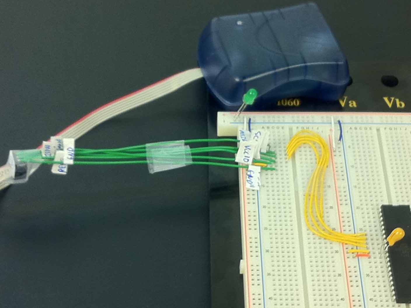
In-system programmer manual breakout. The tape and labels were very easy to mess-up and become frustrated over. And what is that LED doing there?
The new parts kit
I made a whole new parts kit by removing the breadboard, chip extractor, and batteries and added many more parts:
- LED Blue 5mm
- LED White 5mm
- RGB LED Common cathode
- 1k resistor
- 10k trimmer pot
- 10k taper pot
- Knob for taper pot
- CdS Photocell
- Ceramic resonator
- Male header 90 deg
- Male header 2×3 (for ISP adapter)
- USB-to-UART
- Shift register 7595
- Resistor network 1k 11-pin
- LED bar 10-seg
- USB Cable 5-pin
- mega32 ISP adapter
The new price of the parts kit was decreased form $150 to $110, a 26% reduction. Now people do not have to buy the breadboard since a lot of students already had them from previous EE classes. However, if they do, it is still a better deal than Digi-key at $110+30=140 since the breadboard IEEE sells comes with wires!
I also increased the quantity on some of the parts, such as the resistors. Now ten or twenty are included instead of the rather extreme quantities of five or fifty in the previous kit.
I added parts just for the sake of convenience, such as LED bars, bussed resistor arrays, and DIP switches. These simplify wiring so much.

An entire port of LEDs with two components. With discrete resistors and LEDs, this would have taken sixteen components.
My friend Joe and I also co-designed a PCB just for programming the PDIP-40 ATmega32s on a breadboard so that future students would not have to deal with ISP wiring:

Custom-designed PCB to make ISP wiring easier

Look at how clean this connection is compared to the manual breakout above.
I replaced the batteries with a new power source, the USB-to-UART from DFRobot. It is based on the Arduino USB Serial Light adapter. It features a microcontroller that provides a USB-to-UART bridge and a resettable fuse. Now people will not burn themselves on voltage regulators, melt their breadboards from the high current, and can actually send messages to and from their computer Arduino-style. The pinout is pretty much an FTDI cable.
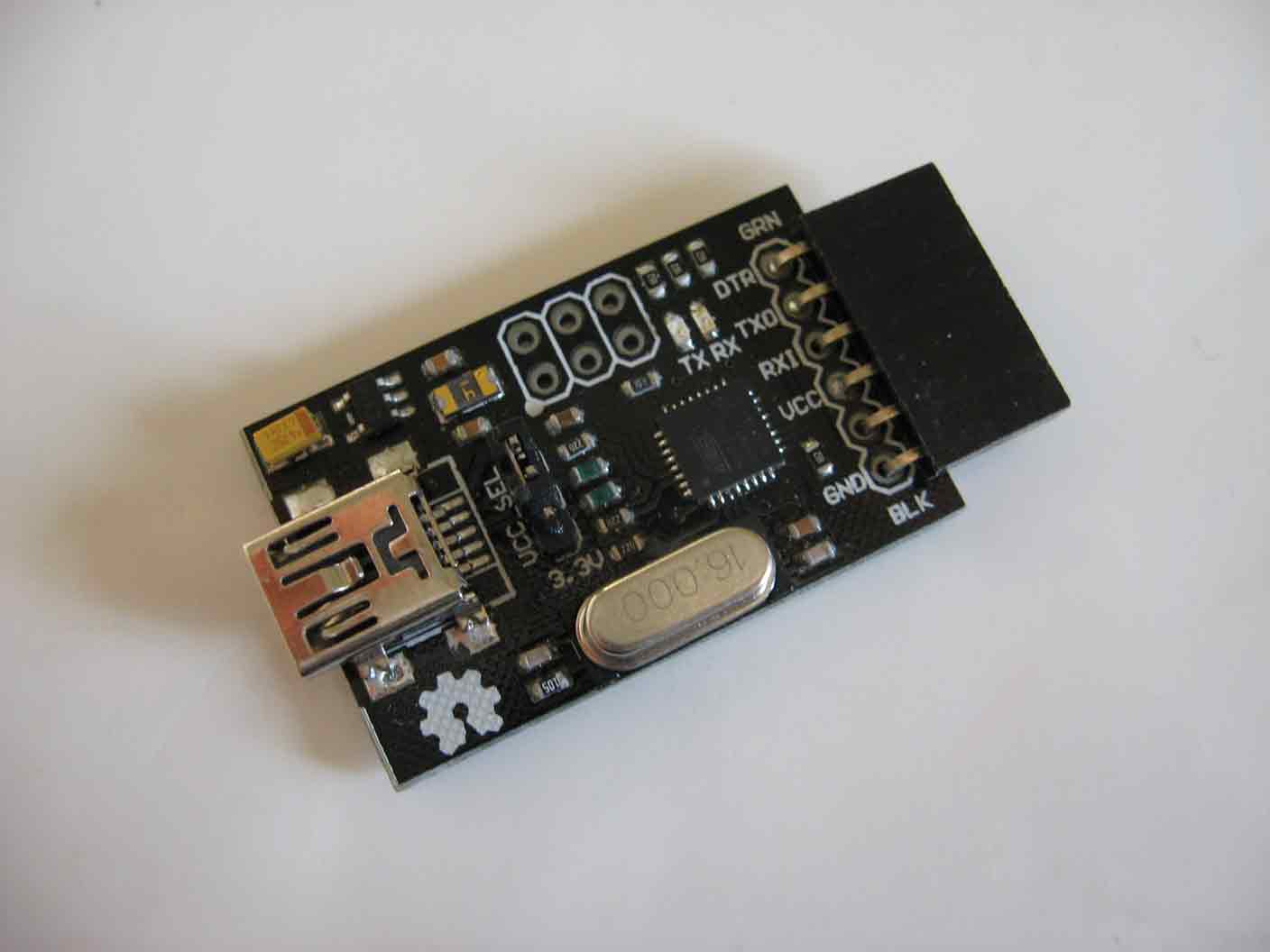
DFRobot USB-to-UART. Notice resettable fuse near 2×3 header.
Creating the new tutorials
These tutorials were created so that I could stop going to lab sessions to inform people how to connect their circuits, especially after I stop being parts manager for the student IEEE chapter and after I graduate. I put them on the IEEE website rather than Google Docs like the rest of CS120B lab manuals since it looks much more professional. The only problem with putting them there is that I will not be able to directly modify them after I graduate, but there should be enough of an IEEE after me to maintain them.
There are already a lot of tutorials online about how to connect every part in the kit, but these tutorials are “far away” and I wanted to have one website where people could look for relevant content rather than having a page of links.
In creating these tutorials, I wanted to make everything as clear as possible regarding the connections that components should have and how they should look on the breadboard. I saw so many people doing very bad things to their circuits even AFTER I introduced the new kit:
- people resetting their microcontrollers by shorting their power rails rather than using the microcontroller reset pin
- people using multiple microcontrollers just so they could have enough pins for their seven-segment displays or LED matrix.
- people directly driving their multi-colored LED matrices from microcontroller I/O pins
- people connecting their LED bars and seven-segment displays, and speakers without any resistance. Surprisingly, all of those components survived a short.
- really bad floating solder connections that did not cover half the pad
To correct this, I include schematics of how to connect everything on almost every page and the reasoning behind it. For example:
The RGB LED is a fun toy to play with. It is common cathode, so connect it with common GND and three resistors, one for each LED. The longest pin is the cathode.The LEDs have different forward voltages, so if you just connect one resistor to the common cathode, only the red LED will turn on because the red LED requires the least voltage (energy) to turn on.
To correct most of the matrix problems, I created a new LED matrices page that shows the different options that people have when shopping for LED matrices. Some people like to wire up their own matrices but are completely unaware of all the calculations necessary. You don’t need to calculate any Laplace transforms, but there are still things to consider.
To correct all the other issues such as people not knowing what to do for their final projects and seemingly not having any choices but some video game with an LED matrix, I created a final project notes page that shows what I have done in the past and many of the peripherals on the microcontroller so that hopefully people can brainstorm more ideas.
I also link to the websites of other people who share the same vision as me, such as Nerdkits, Adafruit, Sparkfun, and of course Arduino.
Sample Code
To top it all off, many of the examples have sample code that people can simply copy into their project to verify working parts and kickstart their development on high-level state machines. Half of it is essentially the Arduino Project adapted for this microcontroller. I also put videos of the output of certain circuits like the shift registe and RGB LED with captions.
Looking forward
In the future, I hope to upgrade certain parts of the kit, such as the microcontroller. Currently Cornell’s ECE 4760 class uses the ATmega1284. This microcontroller has the same footprint as the ATmega32 but with eight times the SRAM and other minor features like an additional UART, more output compare registers and pin change interrupts on every pin. Soon this kit will have that microcontroller as well.
Conclusion
I feel that I have done my best to make use of my knowledge in a positive way. Now I can point to something and say: “I wrote that!”
