
In this video, I provide a complete tutorial on how to assemble your own stair lighting, featuring block diagram, code overview, testing and final layout. Code and schematic can be found on this page.
Table of Contents
Problem Statement
Design Choices
Microcontroller
Input Device
Output Device
State Machine
Code
Schematic
Assembly
Frequently Asked Questions
Problems Encountered
Potential Improvements
Conclusion
Success Stories
Problem Statement
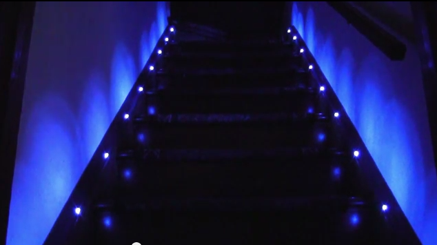
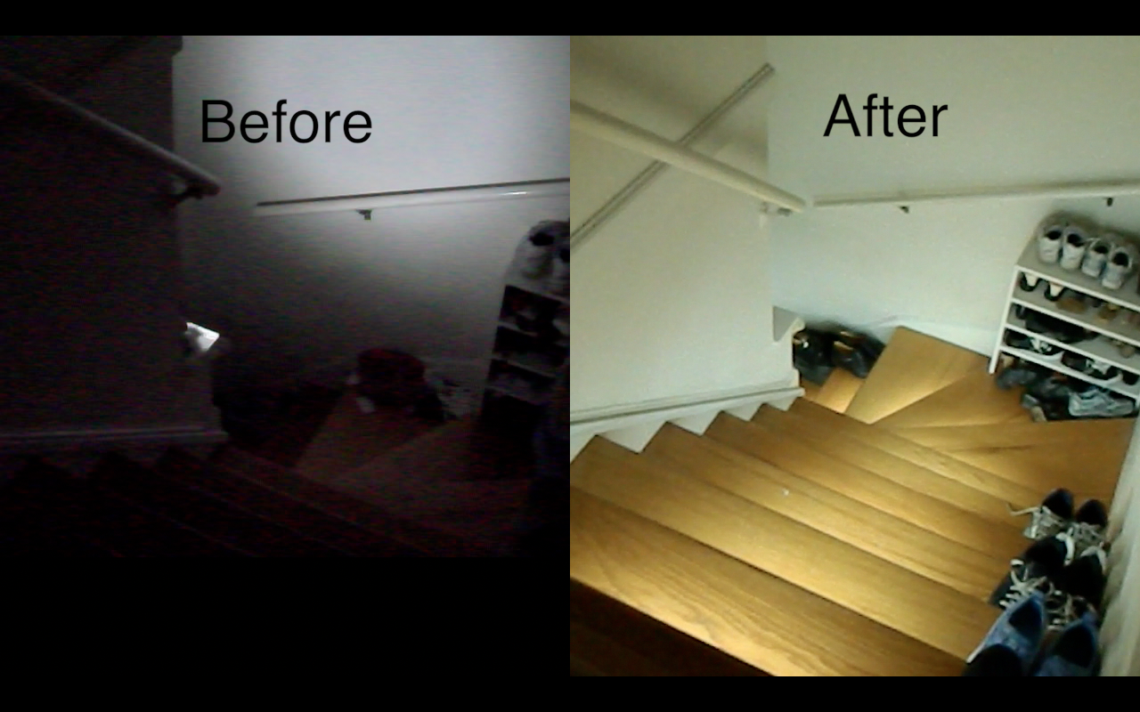
The stairs at night were really dark. It was bad enough that we had to put lights next to it. However, these lights shined in your face and not the stairs. I wanted to light up the actual steps. I really thought the German video was cool, so I aimed for that animation as my goal.
Design Choices
Microcontroller
I chose the ATmega328P firstly because it was on the Arduino. It had the hardware SPI, a ShiftPWM library and good enough speed. If I was mass-producing these, I would probably have chosen a microcontroller with less pins.
Input Device
I had some choices when looking for “person detectors”. I could have used laser sensors, IR beam sensors like they use at the store, or the PIR motion detectors. I initially wanted to use the laser sensors because they show absolute presence vs just motion like the PIR sensors, but they were too finicky. The laser sensors had to be positioned just right on the photodiode, and I didn’t know where to buy the IR beams. The PIR motion detectors actually work very well.
Update 2014-11-09 Since the time of this post there has been a new product in the Adafruit store called a “laser break beam sensor”. If the delay on the motion detectors is completely intolerable then you could try one of these: http://www.adafruit.com/products/2122
Output Device
For output devices, it was clear that I wanted to use the strip LEDs vs the regular point LEDs. I saw some previous implementations like this one and gawked because they didn’t even light up the stairs, only the walls next to the stairs!
This person lit up the wall.
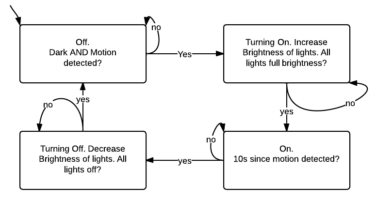
State Machine
Code
Code that runs on the microcontroller may be found on Github: https://github.com/androng/Shift-stairs
Here is a video to help you run the code:
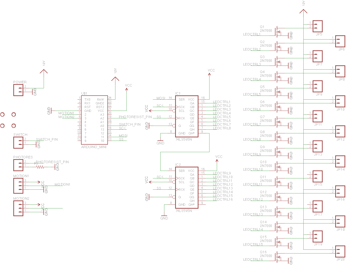
Schematic
I laid out a board but never had it printed. It should be completely functional, but have a look before you print it, especially the minimum distance between traces etc.
EDIT 2014-10-28: I have finally tested the board and it almost works! This was one of my first PCBs and I messed up in my definition of the 2N7000. As a result, you have to solder in the transistors backwards in version 1.0 of the PCB. In version 1.1 this is fixed.
The small rectangle on the left side is a matching through-hole resistor for the photoresistor. I recommend populating the LED headers at the bottom with 2×40 male headers and using black female jumper wires to connect the LEDs. Or you could modify the board to make screw terminals.
Version 1.3: https://oshpark.com/shared_projects/2aD8JaBR
Changes:
1.3
- Fixed “photoresistor always reads zero” problem
1.2
- Added footprint for voltage regulator just in case someone fries the one on the Arduino Pro Mini
1.1
- Fixed backwards transistor problem
- Added more labels for power, motion detectors
- Added labels for MOSFET source, gate and drain just in case you want to use a different MOSFET.


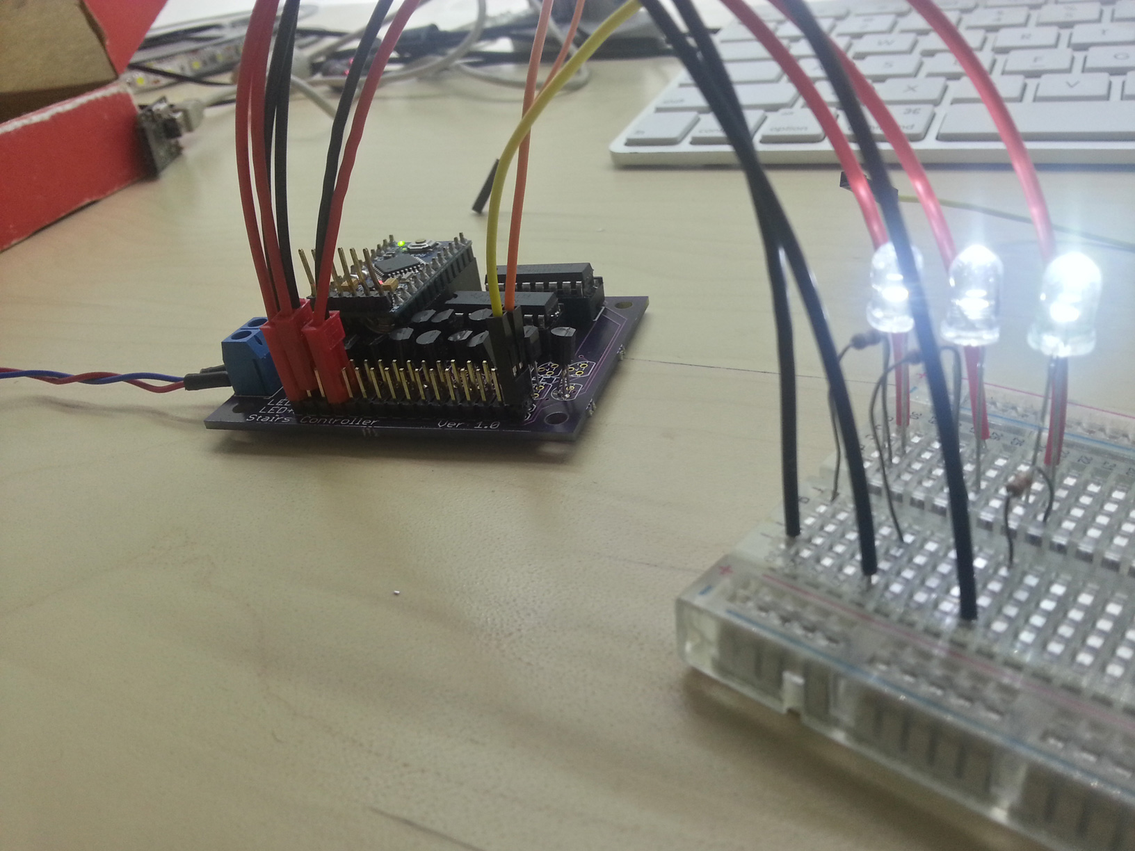
PCB with connectors. I originally wanted to use the red connectors but I didn’t realize they were too thick, so now I recommend the black connectors on the right side.
When you solder everything correctly, this should happen:
Assembly
You will need:
1x Arduino Pro Mini 5V, find on eBay
5m 3528 white LED strip, find on eBay
1x 12V 3A Power supply, find on eBay
PCB, $30 from OSH Park, see Schematic section for link
Enough wire for your stairs, you can also buy similar from Home Depot
2x PIR sensor or Laser sensor
PCB parts:
20x 2N7000 MOSFET or any other pin-compatible MOSFET. SOT-23 packages work well on the PCB too.
1x Single row female header
1x Double row male pin header
1x Single row male pin header
1x (Photoresistor and 10k resistor) (optional)
1x Switch (optional)
1x Screw terminal
2x 16-pin socket
2x 74HC595 Shift register
1x (LM7805 regulator and 0.1uF capacitors) (mandatory)
20x Female Jumper wires (one item comes with several wires)
Tools:
1x USB-to-UART
Soldering iron
Heatshrink and lighter – use the smallest size and cut into 3 pieces each
Wire stripper
Screwdriver
I recommend buying 2 or 3x everything in the “PCB parts” section in case you decide to start over.
Instructions
Assembly video and more detailed instructions coming in the future when I have time
- Assemble Arduino Pro Mini–solder male headers below on the long sides and above on the short sides
- Set jumper on USB-to-UART to 5V
- Connect USB cable > USB-to-UART > Arduino Pro Mini and program it with Blink sketch
- Assemble PCB (refer to photo in PCB section)
- Solder female headers in the “Arduino Pro Mini” slot
- Solder LED+ and LED- with double row male headers
- Solder side pins like “motion” “switch” etc with male headers
- Solder in sockets for shift registers and insert the shift registers
- Insert Arduino Pro Mini with FTDI header in the middle of the PCB
- (optional) Solder in regulator and capacitors
- Assemble LEDs
- Cut a female jumper wire in half
- Put heatshrink on the half-jumpers
- Solder half-jumpers to a 2-conductor wire, then solder 2 conductor wire to LED.
- Connect your jumpers to the PCB male headers
- Repeat step 5 for however many stairs you have
Frequently Asked Questions
How do I adjust the number of steps? Only nine of the steps turn on.
One of my lights doesn’t turn on/off or it flickers.
My lights stay on and never turn off.
One of my motion detectors does not trigger or has many false positives.
Problems Encountered
My choice of female headers as connectors for the LEDs was really bad. The headers are very secure, however all the wires are exposed and it is hard to place one in the middle. Other than that and the point-to-point soldering, I really did not have any problems.
Potential Improvements
Like stated in the video, I would have improved these things:
- Use constant-current LED drivers
- Add second override switch
- Feature: first step always on at night
- Route PCB with FTDI, ISP or Arduino socket on it.
- Made duty cycle vary exponentially with brightness to cancel out the logarithmic perception of brightness. I almost did this, but the effect was not noticable enough for me to spend a lot of time on it. I left it in the code as a large array. (it should be placed in program memory)
Conclusion
I accomplished the objective of lighting up the stairs as well as adding some extra features like daylight detection. After a long time, I finally completed the documentation and edited together the film I captured so long ago! I feel accomplished.
Success Stories
People like you and me have succeeded in banishing the darkness! Publish a video to YouTube, link to it in the comments, and I will showcase it here. Include a link to this page in your video.
Boštjan Perme 2017-02-27
Joshua Mauldin 2016-10-16
troysbucket 2014-11-25:

msvetec 2015-10-04

SG 2015-12-01

Gökhan ÜNAL 2021-07-05

Okay so I’ve got another arduino board from a different suppler on ebay and guess what same thing upload the programme and still all lights come on and stay on,
Made a short video excuse the mess though lol still decorating
http://tinypic.com/r/xeftqb/9
Could you double check for me your transistor? Is it definitely the 2N7000?
Definitely the 2N7000
Hi Mark, Your Project looks good. how did you fix the problem where all the lights stay on when you power it up. Thanks for your help
I have the same issue the lights are on . Any solution? I am using the 1.3 v board
Andrew help please ! I managed to get the components soldered and connected the PIR sensor.but the lights is on .What may be the reason for the same .I have checked all the solder and the connection.
Please advise ……
Is it common for the pro mini to be on even when the switch is on . I mean the red and green LED on the pro mini is ON .Will share pics and videos shortly .
If the lights don’t turn off, then remove the “SWITCH”. That keeps the lights on. The Pro mini is always on when the device is plugged in. Red/green depends on the manufacturer, but one LED means “powered” and the other LED means that the SPI clock is active.
Yes, use a video. Otherwise it’s harder to help.
Hey Andrew.
I managed the get the light working and soon share the video . Just to check in case I need to add additional led for additional stairs how do I do so? .
I have 20 stairs and need additional 4 led output
To have four more steps, you must use another Stairs PCB. Populate Stairs PCB 2 with all the components except the Arduino. Connect the QH’ output (shift register 2, pin 9) from Stairs PCB 1 to SER (Shift register 1, pin 14) on Stairs PCB 2. Connect CLK (Arduino pin 13) on both boards. Connect LATCH (Arduino pin 10) on both boards. Connect 12V to both boards.
Then you would have to change this line to
https://github.com/androng/Shift-stairs/blob/master/Shift_Stairs.ino#L21
const int numRegisters = 3;
const int NUMLEDs = 20;
Thanks Andrew,
Will try and let you know if it works.
Also another query , you mentioned i can use 2N7000 in SMD package. But the pin-out is different. How do i pace the transistor on the PCB.
If the pinout is not compatible, try flipping the PCB and using the backwards pinout.
Hi, I have built the circuit on an Arduino Uno. Unfortunately, the lights do not start when I occupy one of the inputs. (GND or VCC5 +) When I press the switch with GND then all lights go on. Is it because I have not installed a light sensor? I hope you can help me.
The register for my 10 stairs I have so changed:
Const int numRegisters = 1;
Const int NUMLEDs = 8;
I ask for help, thank you
Numregisters should be 2 because 10 LEDs cant fit in just one register.
The light sensor is not necessary and the circuit will function normally without it. However, the light sensor pin must be pulled down with a resistor.
To troubleshoot, you can put
Serial.print("Direc: ");

Serial.print(directionTriggered);

Serial.print("  State: ");

Serial.println(brightnessState);
on line 12 of brightnessSM.ino.
If directionTriggered changes when you change one of the motion detector inputs then the motion detectors are working.
brightnessState should change after directionTriggered changes. If not, the light sensor pin is HIGH (it should be LOW)
Okay so far this is what I’ve got, first half of lights fade on and off and some stay on on switch on,
http://tinypic.com/r/zk68u8/9
Any idea what could be wrong here Andrew, first half fades up and down then don’t work with pir last have come on and stay on,
http://tinypic.com/r/zk68u8/9
Is it really the first half? It looks like the middle. If it is the first eight, the problem is likely a shift register issue–soldering maybe. Have you tried being more generous with the solder?
Hi, is it possible to use the hr-sr04, ultrasonic sensor?
No
Drew, will this PIR work with your setup?
http://www.banggood.com/Wholesale-Mini-IR-Pyroelectric-Infrared-PIR-Motion-Human-Sensor-Detector-Module-p-35759.html
Thanks,
Snap
I have never tried this, but it looks like it will work.
Or this one?
http://www.banggood.com/Mini-IR-Infrared-Pyroelectric-PIR-Body-Motion-Human-Sensor-Detector-Module-p-1015337.html
Thanks,
Snap
That’s weird–why does this one have such a low power consumption? Hm. I think it will work as well.
I’m not sure why the second one has a different power rating. Of the 2, which one do you recommend to be a better fit? Or is there one that you can recommend that will work properly with your setup?
Thanks.
Cheers,
Snap
My project is over successfuly https://youtu.be/EjKNJcM-8PM
Congratulations! Would you mind extending your video to show your wiring and controller?
Sure my hose work on going handrail s and painting works also to be completed after that I will send full video
And also thanks your support Mr. andrew
Code in errors. Plz help and den code my gmail. kedarp9697@gmail.com
What is the compile error?
Hi Andrew I’ve looked over the solder there’s plenty on the shift registers, yeah the first half fade up down the last half stay on, I’m gonna order some shift register and change them see if that’s the problem
hi i dnt knw about electronic but i want to make this can you send me an email for best tutorial for me =) please??
Hi Christian, Check the info at the top. Andrew has listed all the components that you need, and links where you can order the boards. once received, its just a matter of soldering if you have the equipment, all possible within a day, ebay is your best friend. 🙂
Hi Andrew/Readers, I have built my board, and when i power on, the lights shine brightly and then turn on sequentially as expected as per your video, but then the lights stay on instead of turning off. any ideas why this is happening. I have not connected any motion sensors, photosensors or the resistor at this point, i have connected the 7805 voltage regulator and the capacitors and i have also connected all 16 mosfets. i am currently testing with 3 led lights. any help is very much appreciated. thank you so much for your help thus far.
Hooray it turns on! If the lights stay on, then the program is stuck in the sFullyOn state. How long do they stay on?
The first no no that comes to mind is that the motion detector inputs are left floating. I would have used pull-down resistors, but the ATmega328 doesn’t have them. Definitely attach the motion detectors and make sure the motion detectors are “active high”, meaning they output HIGH when there’s motion. If this is the issue, then you should observe the lights turning off sequentially then on sequentially after ten seconds.
If this is not the issue then put
Serial.print(“state: “); Serial.println(brightnessState);
on line 70 of brightnessSM and we can debug
In the software, the only reason this could happen is with the override switch being pulled down. You can check whether this is happening by placing “Serial.print(“state: “); Serial.println(brightnessState);” on line 70 of brightnessSM and then running the program. If it says “state: 4” then it is the override switch and there is a soldering problem.
Hey Andrew,
Which PIR sensors are you using? Are those from parralax some good? https://www.parallax.com/product/555-28027
At the moment I got a RE200B, but can’t get them working.
Yes, those Parallax sensors will work. The Parallax sensor is an entire module, whereas the RE200B is a raw receiver which you still have to bias, amplify and filter.
Thanks for your reply.
Would it be much work to make my RE200B work?
BTW, those parrallax are it bit pricy, are there any other good/cheaper PIR sensors on the market?
Yes, I think it would take a lot of work. If you look at page 6 of http://www.bucek.name/pdf/re200b.pdf, that’s the suggested filter circuit. It’s not really worth it unless you want to play with the raw signal. I am currently testing some PIR sensors from China but I have not tested them yet, so no promises. http://www.ebay.com/itm/131028677440?ru=http%3A%2F%2Fwww.ebay.com%2Fsch%2Fi.html%3F_from%3DR40%26_sacat%3D0%26_nkw%3D131028677440%26_rdc%3D1
Hello Andrew, I got some new 74hc595 shift registers, put them in and still the same, bottom half of the stairs fade up and down and stay off, top half come on and stay on, even the sensors don’t activite the bottom ones? Is there anything else I can try, is there a bug with the v1.3 board,
Sorry for the long delay. I assembled a v1.3 board and it works as expected, so there are no hardware bugs. I did find a software bug that inverts the behavior of the photoresistor. And if you have no photoresistor, the bug completely disabled the lights after the initial fade up/down. But now it is fixed and you can download the latest code. Even so, it should not matter for your problem.
I can’t seem to pinpoint the source of the problem. The half on/half off is definitely an electrical issue, not a software issue. Maybe a trace on the PCB rear is broken. I suggest assembling another PCB. It shouldn’t take more than an hour.
Hi andrew. On my last comment you advised me to enter a couple of lines of code to debug my issue where the lights stay on when powered up. I hooked my project up again today and it seems to be working fine now. However lights 3 and 5 stay on and do not run as part of the fade in/out. Any thoughts. Also i bought some of these sensors but they dont seem to work . Are these compatible
http://pages.ebay.com/link/?nav=item.view&id=221572978745&alt=web
Sorry i got a couple of more questions.
The 7850 voltage regulator gets quite hot. Is this normal
And overall the board seems abit unstable. Like when i place my finger near the motion sensor it triggers it or if i touch the wire.
Thanks for your support
If lights 3 and 5 do not turn on but all the rest do, it’s almost certainly a transistor problem. Check transistors 3 and 5.
The motion detectors look like they should work. The input voltage, output voltage and power usage are within range. Correct polarity too. Try it out in its own program before using it with the stairs lights program.
I sacrificed efficiency for cost and simplicity with the 7805. It becomes hot easily, but it still operates. The alternative is to use a switching power supply like this
http://www.newark.com/murata-power-solutions/oki-78sr-5-1-5-w36-c/dc-dc-converter-switching-reg/dp/72R3616?ost=72R3616&ad=81605889141&selectedCategoryId=&CMP=KNC-GUSA-GEN-SHOPPING-NEW-MURATA-POWER-SOLUTIONS&gclid=Cj0KEQiAxMG1BRDFmu3P3qjwmeMBEiQAEzSDLmAoWGhfWGCKSVYPesn8CerRHul7b05PjBhHDpCf6h8aAlXY8P8HAQ
If the lights seem unstable it is likely to be the motion detector. It quotes “Static current: <50uA" That's really low. It makes me speculate that the output is off when it doesn't detect motion. The solution is a pull-down resistor but I did not include one on the PCB because it's not usually necessary. You can try soldering a high resistance between the motion sense pin and GND. That might fix the sensitivity issues. (high resistance is greater than 10k)
Hi Andrew , I like your project , I’m working on it now. I got all the component what I need. When I finished I’ll share on you site.
I want to ask you , can you make a new project like this with ultrasonic sensor and MM5451 Led driver.
Hi Andrew thanks your nice project. I done my one just now. Another success story for you .
Excellent. Could you show us a quick demo, showing your stairs and your wiring leading to the controller?
Yes I’ll soon. Thank you again for your project.
I use only 1W LED. I didn’t use Transistors. I connect 1W led straight on to the shift register. It’s working fine, and used only 5v PSU.
I like to ask you , can we add a potentiometer to controll of the led running speed ( fading speed) if it’s yes pls show us how to do it.
Hi Andrew, can we add two potentiometers to controll , one for light fading speed and another one for light off delay ? Pls think about and tell me how to do it. Thanks
No. I never included that functionality because the speed only needs to be adjusted once. If you want to change the speed, you have to change lines 18-66 in brightnessSM.
Hi thanks for your quick reply. I m good for electronics but very bad for coding. So I don’t understand how to add potentiometer and code. If you can pls email me how to do it . Millions thanks.
And I found a way without code how to add a LDR just work only at dark time and I can controll resistenc of LDR.
Hi Andrew, thanks for a great tutorial and project. As of 04.03.16 I have successfully managed to order everything of your list so all links are still good except for the adafruit laser which has been discontinued.
I’m a bit unsure about what motion detector to get for, did you have any luck with the Chinese sensors you mentioned in a previous reply? http://www.ebay.com/itm/131028677440?ru=http%3A%2F%2Fwww.ebay.com%2Fsch%2Fi.html%3F_from%3DR40%26_sacat%3D0%26_nkw%3D131028677440%26_rdc%3D1
Any tips?
I will try to help if you have any trouble. I have not tried the motion detectors yet. When I do, I’ll update the blog post with a video.
@Lilly,
Kindly share the circuit diagram, if possible with video explaining the changes.
I am trying to make the code work based on interrupts from http://playground.arduino.cc/Learning/ArduinoSleepCode),
its pretty much in early phase,
Interrupt is working for both top/bottom sensors,
One issue I am facing as of now is that two executions occur for single interrupt,
If the interrupt is triggered for LOW then the execution occurs only one time
If someone has already interrupt based code please share
Can you somehow set the maximum brightness of the LED. Maybe at Arduino code?
There is a constant in the code named “maxBrightness” and it should be adjustable in increments of 5. But the way I coded it, it changes the speed of the animation.
Hey Andrew I made this schame https://speedysignals.files.wordpress.com/2013/07/stairs.png but the problem is that the lights are always on. The brightnessState is always 4, could you help me with this please !?
State 4 is sOverRideswitch. The only way this can happen is if the SWITCH pin is pulled low (marked on PCB by “SWITCH”). Disconnect the switch and the state should change.
Yes after I’ve removed the switch, it works like a charm now. I have another question ;], hope that you can help me with.
PROBLEM: After I activate the diodes from “PIR A”, and after the lights turn off I CAN’T ACTIVATE IT from the SAME “PIR A”.
Good to know it’s working! Regarding the PIR issue, that sounds like a motion detector problem. In other words, there is built-in rate limiting in the motion detector module itself. It is not outputting the signal to the Arduino. The Arduino will turn the stairs on and off again no problem. Try using another motion detector.
I really hate to have to ask this but I’ve committed to this project and I am stuck…
I put most all the components on the board except for the transistors where I put only 3 just to test things. I am not having any luck getting a response other than the first 2 steps are always on and #15 is never on (with the exception of when I reset the Arduino Pro Mini.
Does anyone have any ideas as to where to start troubleshooting?
Did you place “SWITCH” in? If SWITCH is closed then the lights will stay on permanently. Did you solder the motion detectors in? If the motion detectors are not placed, the inputs to the Arduino will be left floating and undefined, which could keep the lights on.
I am also having this problem, i have taken a picture of my setup, and cant understand why the lights just stay on.
have any luck getting your setup fully working?
Wow, I took a long hiatus on this project. I’ll blame it on renovation fatigue!
Anyway, I am back at it and have an update. I was having issues before with my wiring but I fixed that all up. I learned that it is important to let the PIR sensors time to calibrate before testing. Also had one Arduino Pro Mini give up the ghost for no apparent reason…
I am not out of the woods though…everything works great from step 1-9 but 10-16 are unresponsive.
I know that I am getting power there because when I reset the board, all the lights to their customary flash.
I am speculating a software issue but I didn’t change a thing on it so I am not sure where to go now.
Any ideas?
I took a video and uploaded to youtube so you guys can have a look.
Let me know if you see what is going on!
Hey everyone, back from an extended hiatus due to renovation fatigue.
I am back at it and closer than before but still not there yet.
I am convinced that I am either doing something wrong with the upload of the program because I just re-loaded again and now #9 stays on all the time…it was working better in my video below but I seem to have regressed 😦
What program should I be uploading? How many tabs should be showing? Right now I am seeing: Shift_Stairs / brightnessSM / expoDutyCycles.h
I am sure that it will be obvious to someone who has more knowledge than me!
Thanks in advance
Chris
Try changing this first: https://github.com/androng/Shift-stairs/blob/master/Shift_Stairs.ino#L22
Take a video when you’re done and I’ll feature you in the Success Stories section! Make sure to show your controller box and wiring.
Got it! Thanks Andrew!
Wow, how did I miss that when I was scanning through the code!?!
Here is is working great: https://www.youtube.com/watch?v=Jmxi78dtQvA
I have one more question though…is seems that after a few minutes plugged in that one of the LED’s starts to flicker and not totally turn off.It must mean that somehow current is getting through. I checked all the leads and they are good, nothing touching or crossed. I really hope that doesn’t happen when the stairs are all setup.
I am looking at trying to get the stairs complete by January but it will be a stretch since I am not a carpenter by trade but I will be sure to share the results when it is all done!
Chris
If it’s just one light then it’s a hardware problem. You can try replacing the transistor that controls the flickering light or the light itself. Hopes to your January project.
One more question before I go too far.
I am sure it is okay but I was going to run 24AWG wires for each step, there shouldn’t be a problem with that hey? These are only using 200mA or less and from what I see 24AWG is rated for 1-3.5Amps.
I am thinking of re-purposing telephone wires is why I ask 🙂
I was originally going to use 22AWG wire but it is proving to be expensive and/or difficult to find in bulk at the hardware store.
The telephone wire I used in the past was a huge pain because I had to split it, it was really thin and not even full copper, just copper wound around some plastic core. It corroded faster and was more fragile. You would have to split the six conductor telephone wire. Pain.
Radioshack sells 25ft 24AWG 2-conductor for $8. The additional labour is not worth the money savings.
is there a way to share a picture in the comments? also if anyone is willing, i would greatly appreciate some assistance as I am now stuck. board v1.3, have the latest sketch from github compiled and install on the arduino pro mini. trying to test with a 9V series for power. I get the lights to light up, but they are just staying solid and do not act like in the video. I am only using 3 lights for now. also not sure if I am using the correct MOSFET, but it looks like the ones in the picture.
thanks,
I can assist you. Upload an image of the front and back of your PCB to imgur.
Place “Serial.println(brightnessState);” on line 12 of brightnessSM.ino and tell me the output.
I have tested version 1.3 myself and it works as expected. Having the motion detectors disconnected or the switch connected can prevent the lights from turning off–so check those first.
output from “Serial.println(brightnessState);” scrolls :
1
I built 2 board just in case i messed the first one up, have no switch plugged in. I have tried with single light / multiple lights (up to 3) and on both boards the behaviour is the same.
I greatly appreciate your assistance.
Your setup looks correct and I cannot identify anything wrong physically. It’s also strange that the lights are on in state 1, because that is the OFF state. Could it be that you used P-channel MOSFETs instead of N-channel? P-channels would conduct with 0V applied to the gate.
FAIRCHILD SEMICONDUCTOR BS170 MOSFET Transistor, N Channel, 500 mA, 60 V, 1.2 ohm, 10 V, 2.1 V
seem to be the ones i have. so definately N channel. I wonder if the latest source on GITHUB was modified incorrectly? As I just took what was there without any modification to the code at all.
By the way this is a great project Andrew, if you are able to help me get it going, i will gladly do a full step by step write-up for the newbies like me who could use a little help and document the snags i ran into.
Thank you for providing this information. I looked up your transistor and found that you inserted it backwards. See picture: http://screencast.com/t/z1j6l3dqj57 You can still use the BS170, but you have to insert it opposite to what the silkscreen shows.
Here are a couple more pics, i ended up getting another pro mini (osepp) in case something was maybe wrong with the mini-pro, and same result.. I also ended up getting a 12 volt power supply, thinking maybe with the 9volt battery pack was not enough power… still no dice and the lights just stay on.
Andrew, thank you so much for taking the time to assist. The MOSFET’s were backwards, I didnt even think to check the schematic, lesson learned…
Again thank you so much, all is working and i have adjusted timings and top and bottom sensors are working well 🙂
You have made my day, thank you again for all your help. You are Awesome!
I love assisting and succeeding! Would you like to take a quick video of your circuit and your stairs lights so I can feature you in the post? It’s much easier than a write-up.
I sure will, it’s the least I could do, will take me another week or so to finish routering under the stair nosing so LED strips are totally hidden and build out the pretty box for components, but I definitely will!
Stay tuned 🙂
Andrew,
I am done Andrew! and so happy with how it turned out, making a video and taking pictures tonight. would you like me to send to you to post or just post on Imgur?
Also before i finish, 1 last question, I must be going crazy, what is the variable in the code that slows down the lights? (how fast they light up) I can adjust the duration they stay lit just fine, but i keep playing with different things and cant get the speed at which each tred fades in. I was able to slow it down using println statements but there must be a better way.
Disregard, i figured it out !
made a little album of the finished product, came out excellent, and custom box to keep it all mounted in nice and tidy. the second controller is now for another set of stairs, to be hooked up later…
and a little video… sorry no music ;-(
Special thanks to Andrew for the assistance and the great controller.
FAIRCHILD SEMICONDUCTOR BS170 MOSFET Transistor, N Channel, 500 mA, 60 V, 1.2 ohm, 10 V, 2.1 V
seem to be the ones i have. so definately N channel. I wonder if the latest source on GITHUB was modified incorrectly? As I just took what was there without any modification to the code at all.
is it possible to get a picture from someone of an assembled board, the 1 pic by the OP is hard to see everything, and the little video only shows a small section of the board.
If anyone has or the OP has that would be great.
thanks,
Dave, I know this is old but I wanted to ask. How did you run/hide the wires?
I bought this
A+ Electric 235″+80″ Cord Cover… https://www.amazon.com/dp/B08664NLCH?ref=ppx_pop_mob_ap_share
@Andrew, weird I cannot see a reply link under your comment about what you purchased. Anyhow, I wanted to do it without adding a cable channel. I was looking at going through the step riser, but the back of my staircase is closed off.. I guess I’ll have to cut cut cut into the drywall…
Thanks for the prompt response Andrew.
Does anyone see possible to make something similar but skip the cables? make some kind of wireless conection for each light? This help to make it fit any size stairs.
Wireless connections are not fun. The wireless channel is not 100% reliable. The wireless devices require batteries that have to be changed. The wireless devices are more expensive because now you need a radio on each step. Compare this to plain wires that have none of these problems. The only thing you gain is that the lights can be moved and no wires have to be installed. But if the steps are not going to move, then why bother with wireless?
Hi Andrew. is it possible to use a stair pressure mat instead of a motion sensor (http://www.maplin.co.uk/p/stair-pressure-mat-fk79l) so this can be placed under the carpet. Thanks
Yes it is.
Connect the pressure mat to 5V and the middle pin of MOTION1 on the PCB.
Connect a 10k resistor to GND and the middle pin of MOTION1 on the PCB.
Do the same for MOTION2.
Tell me if this works.
Andrew, when you say “Connect a 10k resistor to GND and the middle pin of MOTION1 on the PCB.” do you mean each should have it’s own 10k resistor between the pcb and the pressure mat (or in my case the laser sensor) or that there should be a single 10k resistor connected between the GND and middle pin?
I am using http://www.waveshare.com/wiki/Laser_Sensor for the top and bottom sensor. The top sensor is very close to the board and seems to work well. The bottom sensor, however, is a long run and appears to be causing an issue where the lights remain on.
Great project! Almost done… I appreciate any help/advice you can give.
The sensor you purchased already has a pull-up resistor, so no additional resistors are needed. If the bottom stairs sensor does not work well, first I suggest swapping the top and bottom sensors to make sure you don’t have a bad sensor. Same behavior after swap means the wire to the bottom sensor needs to be thicker or the bottom of stairs need an environment change to accommodate the sensor, like a reflector on the other side of the step. Different behavior after swap means you have a bad sensor.
Post a video when you’re done =) Be sure to show your controller box with wires.
Hey Andrew…
Thank you for your help! I used a heavier gauge wire on the bottom sensor and it works great! Here’s a video: https://youtu.be/xrlXkuTzJhE
Great project! Thanks, again!!
Wow. Your installation looks great and your video looks better. Nice job on the editing and the presentation. I’ve placed you under my Success Stories part of the post.
Hi Andrew,
On the board there are few things that I dont understand. Maybe you could clarify (perhaps silly) issues.
There are two blocks C1C2 and R1 on the board, but there is nothing in the part listing that would fit these slots. Are these important. Looking at some of the prototypes I see that people have left these slots empty. Also the C1C2 was added in v.1.3 I think.
R1 is completely unnecessary. It is for the analog circuit that prevents the lights from turning on while its bright, saving energy. C1 and C2 are the decoupling capacitors for the voltage regulator. I recommend placing these but they are not required.
Hey Andrew I have a question. How can I remove the delay time between activation of the lights. Now when I activated the lights they turn on then turn of, but if I tried to activate it immediatly, I couldn’t. I have to wait some time.
The microcontroller allows immediate re-activation. The artificial delay comes from the motion detector modules. If they don’t output another rising edge, the microcontroller will not activate.
Show off your setup when you’re done =)
Yes sure Im almost done, just want to make some calibrations ;]
Hi All
I just wanted to ask a question do the pirs switch off the lights after being triggered or is it just a timed interval?
I am looking to do the project but for an outside light over 10m with 1m at a time, pirs to trigger both end the same as the stairway
Thanks inadvance
It is a timed interval of 30 seconds by default. After 30 seconds the lights turn off. When you say “light over 10m”, do you mean 10m of strip lights? The 2N7000 MOSFETs can only handle 200mA per MOSFET. Make sure each channel is below this or buy another transistor that can handle more.
Thank you for your reply Andrew
yes 10m of strip in 1m sections , I was going to convert the 2n7000 to a TIP120 circult that I use for most of my arduino projects, I have never used a shift register before but Im guessing it gives a 5v high ouput when switch on?
Its a bit extreme for an outside light but as you said in the video “I wanted more” lol 🙂
I hoped It would switch off as the second PIR was activated but when I looked at the code it seemed as tho it was timed and you have now confirmed that
Thank you
Just one other thing, why did you feel a constant current LED driver to be used?
The current vs voltage curve of LEDs without resistors is exponential. At a certain point this means that for small LEDs, 2.9-3.0V -> 200-300mA. A constant current supply, regulated to 1%, would be much better at regulating the LED than a 1% constant voltage supply. For strip LEDs though this doesn’t apply since there are so many of them in parallel and there are resistors. Common voltage is the better choice with strips. Constant current is better for one series of LEDs at a time.
Hi Andrew, I’ve downloaded the code, I’ve complied it and when I upload I get a response back saying programmer not responding, I’m new to arduino, any help would be appreciated. Thanks
Hi Andrew don’t know if you can help me but the code complys but when I try to upload the program on to the board it says programmer not responding I’ve checked that all the wires are in the right place, I’m wondering if there is a boot loader on the arduino board, any help would be much appreciated
First, check your COM port. Tools > Serial Port > COM6 or whatever the highest number is. It shows up in Device Manager under “Ports” when you plug in the USB-to-UART. If it does not show up, you need to install drivers. Next, check your board. It should be “Arduino Pro Mini”. The Arduinos come with bootloaders so that they can be programmed over UART. Now you should be able to program the Arduino.
I’ve done all of this and still programmer does not respond, would this be a case of a duff arduino
What did you see after trying my suggestions? Does the COM port show on your computer? Does the LED on the Arduino Pro Mini blink? Does the LED turn on briefly when the Arduino is powered on?
It could be a destroyed ATmega328P. But it could also be other things. The fuses could be burned incorrectly, requiring a 5V 16MHz Board selected instead. There could be no bootloader on the chip. A power wire or power diode could be missing or fried on the Arduino PCB.
Sorry Andrew, yes it shows up in ports like it should, the led does blink on the the board once plugged in, I’ve tried using the 5v 16 mhz board as well, I’ll order another one and try that,
Hi Andrew I’ve finally uploaded the code, apparently I was using the wrong board even though I chosen pro mini, the next problem I’ve bumped in to is that light 1 2 3 4 6 7 8 start off bright and them go to a dim light and lights 5 9 10 11 12 13 14 15 16 all stay bright, they don’t fade up and down? Can you help with this problem ?
Thanks in advance
Hi Andrew,
Can you add more than 2 shift registers if you want to run more than 16 LEDs?
great project and instructions BTW.
Yes. But I didn’t make it easy to solder a third register. You’d have to place it off the PCB.
Hey Andrew, great project and tutorial!
I would say that I am totally noob at electronics, I have only soldered few leds together and powered them up with batteries. Arduino and PCB is absolutely new to me (I’ve been learning about them 3 days now, downloaded Arduino program etc.). But I have decided to step into it and hopefully I’ll achieve this setup you uploaded here.
I am starting to gather stuff to light up my stairs as well. I have 14 steps, each is between 83-122cm. Total lenght for led stripes will be 13,32m. Will order LEDs from ebay, 3528 and 24W/5m, 0.35-0.4A per meter. I am bit confused about mosfets, as I read, each is 200mA. So I need 2 Mosfets per 1 meter?. So ~27 pieces? Should I replace them with something stronger? OR maybe I am getting something very wrong here? 😀
I think there will be more questions coming 😀
My best regards,
Rainer
Hey Andrew, great project and tutorial!
I am very noob at electronics, I have only soldered few LEDs together and powered them up with batteries. Arduino and PCB are totally new to me (have learned aout them past few days, downloaded Arduino program and tried you code loading etc.) But I have decided to take this step and hopefully I achieve the same result you have uploaded here.
I am starting to gather stuff to light up my stairs. I have 14 steps, each between 83-122cm. Total lenght for LED stripes will be 13,32m. Probably will order LEDs from ebay, 3528, 24W/5m and 0.35-0.4A/Meter. Bit confused here with mosfets, as said each of these hold 200mA. Does that mean that I need 2 of them per 1 meter, 27pcs total? OR I am getting something very wrong here?
Thank you in advance and more questions coming I guess 😀
My best regards,
Rainer
That’s correct. You either need two 2n7000 transistors per meter, or one per half mater. Honestly I wouldn’t put more than 0.3m on each step, its just not necessary.
Alternatively you can replace the 2n7000 with something with a higher drain current.
I can answer more questions.
Would these motion sensors work on your setup? They look nice and would be easy to install.
http://www.ebay.com/itm/DC-12V-LED-Body-Infrared-PIR-Sensor-Motion-Switch-Automatic-On-Off-Strip-New-/252550083359?hash=item3acd28731f:g:It0AAOSwOyJX35xv
I am not sure because I have never used them. But just from the picture it looks like they would work. You would have to figure out which wire gives the motion signal.
Hey Andrew! Most of my supplies have arrived but still waiting my Arduino board. Assembled two PCB’s and as soon Arduino board arrives, I will program and try it. But one question about powering it up. I ordered 12V power adapter. As I see, some guys here tested it with 6×1.5V batteries. And Arduino itself is 5V? Can you please explain me this topic a bit, please? 🙂 Would not want to burn something. I will make photos/videos as well, when all assembled.
Thank you!
Never mind, got myself clear with voltage topic 😀
Still having issues? Or is everything ready?
Well, I finally got everything I need to make it function…or not. Probably it’s some bug with sketch uplod or Arduino board but I’ll ask Your opinion. At first I though that motion sensors are not working but just checked them separately and seems that they are okay. So when I power it up, they flash once, then light up and then fade out and stay.
Here’s a quick video I made:
Probably an issue with code uploading, but I’m not sure. I didn’t change the Arduino, just paid more attention to timing the reset just before the upload.
Wohoo, today I tried blink sketch with different delay times to make sure I upload the code correctly. Everything was working fine and uploaded stairs sketch on and it works as well. I just had this manual reset timing issue because I accidentally got usb without DTR pin.
Great that I got it working, now I just have to install everything on my stairs.
Nice. What resolved your earlier issue? Was it just a matter of replacing the Arduino?
Well, i got my leds installed to stairs and lit them up first time with 12v . They first lighted up, then faded out like before but no action after. I reconnected power supply and the lights just stay on. Tried to restart Arduino but it does not work and board itself got really hot. I assume that i burned my board? I have regulator installed but no capacitors. Wondering, what went wrong… and have to find few new Arduinos.
If all the stairs fade in and out then the arduino is working. At least for a short while. If the board gets really hot, that’s really bad. It means something is heating/shorting. Add the capacitors and change the regulator. If your power supply allows, try using 10V before the full 12V.
They faded in and out on first power up only. After that they just turn on and stay on if I connect them to power. I’ll buy new board and try to fix these possible issues.
Got new board and installed capacitors and it works 🙂 but after some times it will light itself up (from one side only) allthough there is no motion near sensor.
But happy that it works 🙂
Little video
Nice job. Would you like me to post it under the “success stories”?
Well, not successful yet… I disconnected motion sensors to put wires through the box. And after that it doesn’t work properly. It only lights up 2-3 times from one PIR only and then nothing. After some time same story: lights up from one side only, few times and then again silence. Few times it all works correctly, then one side fails and after that other side fails as well. Now that I am upstairs and nobody near sensors, it lights itself up after times. I controlled sensors separately on breadboard with one led and they both work like they should. At the moment they are both on jumper wires so wires cant be issue. I re-uploaded the code to Arduino. But I am out of ideas, whats wrong with it now.
I looked at your picture and see no errors. But from your problem description I believe it is a motion detector problem. I don’t know what you mean by “one side fails”. Do you mean it stops triggering?
Try using two jumper wires to connect the LED to the motion detector output and the Stairs PCB at the same time. That way you can identify whether it’s the Arduino or the motion detector that is falsely triggering after two times. I have the feeling you will have to change the motion detectors.
Well, tried another set of same sensors but still same issues. Sometimes they just don’t trigger the lights and sometimes they trigger even there is no movement. How much the sensor wire lenght and and diameter can be the issue? Maybe should try laser sensors instead of PIR’s…
There was another person who solved his issues by using thicker wires to the bottom motion detectors. Try using some 24 AWG wire from Radioshack or an ethernet cable. Try swapping the sensors too. If one sensor work and the other does not, then swap them. If the one with the shorter wire always works then it’s the wires that are the problem.
Hey Andrew! Might say that I got it work, but these motion sensors are sketchy. Tried different ones but always issues that sometimes it triggers the lights itself and sometimes it wont detect motion. Would it be possible to use this kind of laser sensors: http://www.ebay.co.uk/itm/For-Arduino-Laser-Sensor-Pipeline-Counter-Smart-Robot-Obstacle-Detection-/291977515965?hash=item43fb3753bd:g:gbQAAOSwEzxYWSyB
hi Andrew, I have a slight problem, lights 1-8 come on bright and just dim slightly, lights 9-16 come on bright then flicker constantly, I’ve looked over all the soldering but all that seems to be fine, I cant seem to find any problem with this at all, any help will be much appreciated
Try editing this line first: https://github.com/androng/Shift-stairs/blob/master/Shift_Stairs.ino#L22 Does it fix the problem?
Sorry for all the questions Andrew, what do I change the line to, I’m determined to get this project to work
Change it to the number of stairs you have. For example, if it’s 14 stairs, then try NUMLEDS = 14;
Hi Andrew thanks for your reply, I’ve changed the number of led but it’s doing the same thing 1-8 come on bright and then dim slightly and 9-16 come on bright and then flicker, is there anything else I can change in the coding ?
Hi Andrew, I’ve now got it to work, only problem I have is that number 5 light stays on, and that the lights activate them self from the top senor, every min or so they’ll activate with out anyone walking past any idea on what’s going on ?
If the top stairs sensor does not work well, first I suggest swapping the top and bottom sensors to make sure you don’t have a bad sensor. Same behavior after swap means the wire to the top sensor needs to be thicker or the top of stairs need an environment change to accommodate the sensor, like a reflector on the other side of the step. Different behavior after swap means you have a bad sensor.
Hi! I’ve gotten my controller working (sort of), but the Arduino gets pretty damn hot rather quickly. I was just wondering if this is normal or if I’ve messed up, which is probably highly likely?
If the Arduino gets hot it is always bad. Check the voltage on the Arduino VCC pin. If it’s over 5.5 then replace the Arduino.
Make sure to eliminate the cause of the problem before you install a new Arduino. Yes this is vague but I need to see and measure your circuit before I diagnose. Check your voltage regulator.
I measured the VCC on the arduino, it’s at 5 ish volts. The regulator seems to be in order as well. Gets a bit hot, but I guess that’s to be expected. The circuit is behaving weirdly though. It keeps the lights on all the time and flickers a little at random.
Hi Andrew
Just thought I would send you the link for the project I did based on your stair lighting and I changed it , the arduino sketch i didnt change
Thanks for all your work
Nice thorough explanation. A bit long for video format but useful. Good job repurposing the code!
hello…i m intrested in staircase project but what are the circuit diagram and components required…..
Interesting article and would be great fun to make one. Can I use L7850cv MOSFET instead of 7850 ?
I’m pretty sure you meant L7805CV, not L7850CV. Yes. you can use it.
Hello, I tried using a IR distance sensor for my prototype, and when the sensor is triggered from long distance, sensor’s out LED is dim and the light sequence is running very slowly and I think it won’t turn off at all.
if I put obstacle close to sensor, around 4 cm, then sensor’s out LED is back to normal brightness and sequence is back to normal speed.
Can you find out why light sequence is running slowly? Also can you share the EAGLE file, because I want to make pcb with 3 74HC595 Shift register. Thank you
Dim LEDs typically mean that the power supply is lowering its voltage because the power draw of the circuit is too high. I would need to play with the sensor you are using to understand it completely.
The EAGLE file is in the Github link in the post.
Hello can you send me the 3 74HC595 PCB project? kacper.korczak123@gmail.com
there is no “3 74HC595” project. there were two maximum.
Hi,
Thank you for sharing this project! i was able to make my own controller and so far everything works great! im working on pir / photo sensors enclosures before i will install it on actual stairs (I’m open to any suggestions). I do have one question. how can i dim led strips???
There are two ways. Hardware method and software method.
1) Recommended method: Hardware: Use a lower voltage power supply. Instead of 12V (maximum), use 10V 2A power supply or 6V 2A.
2) Software method: Change this line: https://github.com/androng/Shift-stairs/blob/master/Shift_Stairs.ino#L19 However, LED brightness is perceived by the eye logarithmically, so instead of levels 40, 80, 120, 160, 200, 240, 255, the levels are 1, 2, 4, 8, 16, 32, 64, 128, 255. Further I think the way I coded it, you have to choose an increment of 5. So choose 125 or 65 or 30 as your brightness levels.
Ad here it is:
Thanks Andrew
Congratulations! I added you to the post.
Awesome !!!!
looks great! how did you make that groove in stairs tread? to fit that led channel? whats you PIR sensor?
I was just lucky to find this page (instruction) before I buy a new stairs. So I was just ordered stairs with LED channels under each stair and woodworker made this for free and he also know how to do all the channels for the cables 🙂
I buy alu profiles for LED in a local store, it wasn’t cheap (arround 70 EUR for 12x1m), but it was worth it, it looks great and plastic cover also diffusing the LED light.
PIR: I buy them from ebay: Adjust IR Pyroelectric Infrared IR PIR Motion Sensor Detector Module HC-SR501
http://www.ebay.co.uk/itm/Adjust-IR-Pyroelectric-Infrared-IR-PIR-Motion-Sensor-Detector-Module-HC-SR501-/281678216287?hash=item4195547c5f
Mr. Preme,
Really smart and clever! Can you please post a picture of the channels cut in the stairs and where you put the board and sensors?
Thanks
Tella Puli
Hello, is there a possibility to make it with up to 24 steps? I’m a absolute beginner in arduino projects and i want to try this in my apartment, which has a stair with 20 steps. The schematics seems to me to take 16 steps maximum.
I really like this project!
The schematic only allows 16 steps. To reach 24 steps, you would have to modify the schematic and make a new PCB. Then you would have to change this line to
https://github.com/androng/Shift-stairs/blob/master/Shift_Stairs.ino#L21
const int numRegisters = 3;
const int NUMLEDs = 24;
Hello Andrew,
I came over your web site while I was searching a solution for my stairway. I would say that I admired your patience helping over all other people who are trying to build your solution. Needless to say how open minded you are , sharing your passion with all rest of the world..
Before moving in to building phase, I have some questions which I’ll be please if you help me sort them out.
1. I would need to use in total 10mt of led strip each varying 70cm to 90cm. In total 15 steps. While I was reading early posts I came over the following feedback of yours :
“Alternatively you can replace the 2n7000 with something with a higher drain current.”
Can you please tell me what could be that alternative? I saw that Steve had intended to use TIP120 which I haven’t seen any feedbacks of him on this matter since. Is that suitable? if not what is your advise?
2.PIR Sensors – I saw that Boštjan Perme has used Adjust IR Pyroelectric Infrared IR PIR Motion Sensor Detector Module HC-SR501 for this, which I intend to use. Any objections ?
3. Choice of LED strips : “Use constant-current LED drivers”
I’m planning to use either the following led strips :
http://www.befr.ebay.be/itm/Integral-IP67-5M-Flexible-LED-Strip-12V-Constant-Voltage-3528SMD-6500K-350lm-M-8-/222420887434?hash=item33c951678a:g:gW8AAOSwfVpYsNXG
or
http://www.befr.ebay.be/itm/282286933732?_trksid=p2060353.m1438.l2649&var=581352772039&ssPageName=STRK%3AMEBIDX%3AIT
I saw that constant-current leds are expensive than the others. I know that what something worth is relative for each of us, but do you think that it is worth to buy the constant current?
Thank you so much in advance taking your time….
You can buy either of the LED strips you linked. If you only require 90 cm on each step then (0.09m/step)*(6W/m)*0.09m*(1V*1000mA/1W)/12V = 45mA per step. This is below the maximum drain current of the 2N7000 so you can still use it.
I said that I wanted to use constant current LEDs but if there are resistors on the LED strips then they become a lot more linear, so the constant current is not necessary. The constant current is only necessary when switching just a high power LED with no resistor.
No objections to the PIR sensor. It looks like it should work. But he is having issues with them. You might want to try two kinds.
Hey Andrew,
I am.working on my second board but now I am.using some.smd components . Everything is soldered and when I tried to power on the device the lights stay on. I have connected only one PIR sensor.
Please advise
Check the source/gate/drain of the transistors. If the source and drain are backwards then they will never turn off.
Does the device do the “fade up/fade down” sequence before staying on?
Hello Andrew
First of all, thank you for sharing the resources of this project!
This project really enthused me and I hate to finalize it you inspired me a lot.
I have a question, my editing is finished and I passed the tests.
Unfortunately everything does not happen as hoped, indeed when I turn on the card: the LEDs light up immediately and never goes out …
I have tried my l thing before you bother: I tested with and without PIR, I changed the swicht of my PIR, I tried without the arduino and the result is always the same, I always have the LEDs on.
I post you a small video to see better, if it must I also have pictures.
Thank you in advance cordially Fred78
Nice job so far. What transistor are you using? May I see the datasheet? Usually if the LEDs don’t do the initial fade-in/fade-out, the transistors are backwards.
Thank you Andrew for this very fast response and your encouragement!
My transistors are 2N7000PD I hope I was not mistaken when purchasing.
I have not found a technical sheet specific to the 2N700PD but I suppose it is a classic 2N700.
I add some photos of the assembly if necessary.
https://www.dropbox.com/sh/owb52qhly6tzmle/AAAjhuhYFXQm9uyhR0V1pq2da?dl=0
I could not find anything on “2N7000PD” either. It could be that you purchased P-channel MOSFETs instead of N-channel because of the “P” in the “2N7000PD”. If that’s the case then there’s nothing you can do except buy new transistors. If you want to confirm my theory then you could set up some simpler circuits that discern P or N-channel and source/drain pin swaps but without a datasheet it’s hard to troubleshoot further.
I will follow your advice and buy new transistors tomorrow, I keep you informed of the continuation.
A big thank-you !!!
I just found that I received 74HC165 SHIFT REGISTER instead of the 74HC595 SHIFT REGISTER …. I guess there is a good chance that the origin of my problem is there, you think what Andrew?
I will still buy 2N7000 N channel tomorrow and I will also take 74HC595.
Nice catch. I didn’t see that. Yes, that shift register works in the reverse direction. You’ll want to replace that too.
Out of stock at my supplier, I order the 74hc595, I keep you informed of the result of the I receive them !!
It is there i received the right components, and it works very well !!!!
Thank you andrew I finalize the assembly in the stairs I will post the result!
You really have been nice to have made available your work and to have answered my questions !!
Hi There.
I just finished this project yesterday and everything works as expected ( and that on bread board )
THe voltage regulator and the arduino are getting hot so probably i made some mistake in the regulator circuit. But one question that i have is why are we sending 12v and vcc to the arduino? would vcc or 12V not be enough?
12V is sent to the regulator and 5V is outputted to the Arduino. The linear regulator will get hot pretty quickly because with 12V-5V, it’s only 40% efficient. But if the power usage is low then it still functions and doesn’t explode. If you can swap in a switching regulator I would do that.
Good evening Andrew, first thank you for your quick reply. I changed the register to 1/8 because I wanted to test it first with a 74HC595 on a board. I switched the light sensor with a pull down 1kohm. On the inputs 2 and 3 I have a 12kohm resistance. There I then give to test a high signal. The leds shine as they should. Only with the transistors I use the LEDs light up almost simultaneously at the same time and go out almost simultaneously. I think that I times other transistors will test and put on the collector a 12kohm with diode resistance.
A question I have still: What value can be changed to change the running speed of the led?
Hi Andrew,
thanks for designing and programming this awesome unit.
Ive build two but had some issues with the PIR’s (due to the environment)
Ive tried to solve this with other sensors GP2Y0A21YK0F
the Work awesome but just up to 25 centimeters
The problem lies in this the analog voltage out will range from 3V when an object is only 4″ (10 cm) away and 0.4V when the object is 32″ (80 cm) away.
Unfortunately the Arduino has High on its input only when 3v is send to it.
https://www.arduino.cc/en/Reference/Constants
Im trying to read the code, and can read some of it, but i have no arduino experience and its and couldn’t quiet get it unfortunately.
Could you spare me some thoughts?
thx
Thijs
I hate to say this but you need to buy another sensor. 2.5V is the minimum for HIGH reading on the digital inputs and if 3V is the maximum that sensor outputs then you will have to be really close to the detector. I don’t recommend that Sharp sensor. It’s expensive and not suited for this application. Buy a PIR instead.