
Two years ago, before Lockitron and all of its competitors arrived, I went to college. During college, I created many prototypes of an electronic door lock that I detail below.
Table of Contents
Problem Statement
Design Choices
Microcontroller
Input Device
Proximity Detector
Door open/closed detector
Output Device
Lock actuator
Servo Motor
Morning Industry Deadbolt
Solenoids
Internet Logging
State Machine
Code
Schematic
Problems Encountered
Morning Industry Deadbolt
Deterioration from weather
Arduino Freezing
Fridge and Exhaust Fan
Potential Improvements
Conclusion
Problem Statement
I stayed in a dorm called “Pentland Hills” where you had to open three doors to enter your room. The building door had an RFID reader where you could simply tap your card. The suite and room doors required swiping. The suite door was usually left open, so there was only the room door left. I never wanted to swipe again. Therefore, the electronic door lock was born.

The beautiful Pentland Hills.
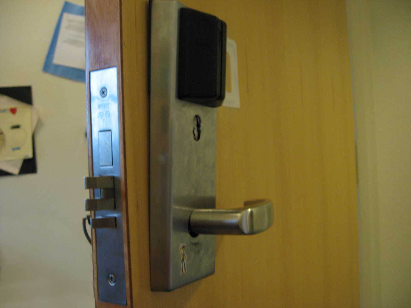
The “swipe” lock that I wanted to convert to RFID.
There were several reasons for this project. In addition to the above paragraph, I wanted to rid myself of last century keys. They made holes my pocket, made noise, scratched whatever else was contained with them and were not fun to use in the dark. Secondly, when I moved into an apartment, I used a deadbolt to lock the door. This meant I had to use a key when both entering and exiting. Using a key was the worst thing I could be doing with my life and could be easily automated.
The lock needed these features:
- Unlock when either I or my roommates walk up to it
- Automatically lock a deadbolt when the door closes
- Report all “access granted/denied” and “door open” events to the Internet.
- Lock still needed to be operable by school housing administration
- Lock must be operable manually with a key from the outside and fingers from the inside (no “push to exit” button)
A side effect of building your own door lock actuator is that you get to choose whatever triggers it. This means you can create as many keys as you want in whatever form you want. I took this to mean that I could hide a lockout tag somewhere nearby in the same fashion as a spare key and not have to call access control when I was locked out.
Design Choices
Microcontroller
I actually had several prototypes for this lock. My first prototype used my first microcontroller: the Arduino Duemillonove (made in Italy!). (Fall 2010)
Prototype 1. Notice the two RFID readers, one HID and one Parallax. Notice the partially open door lever pulled by a servo. All powered from the wall.
My second prototype used a bare DIP ATmega328 because I wanted my Duemilanove back and the ATmega328 fit nicely on a breadboard. (Winter 2010)
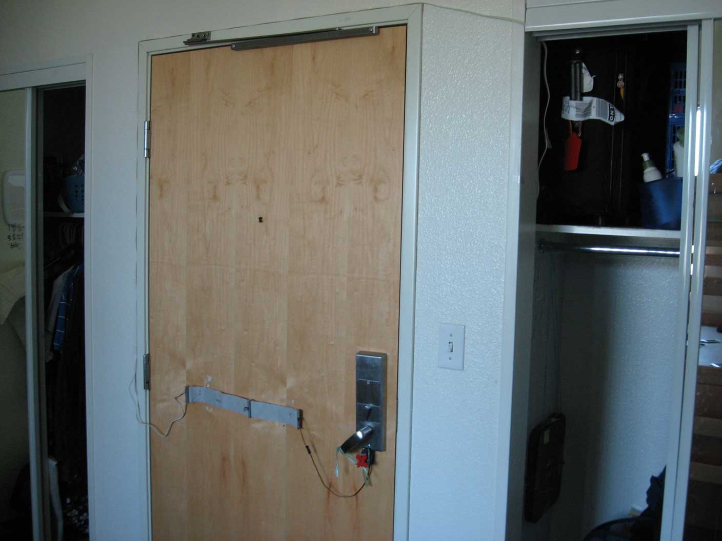
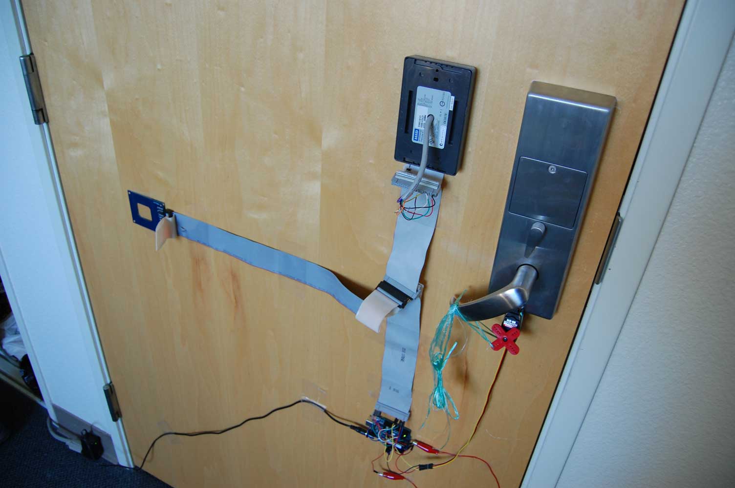
Prototype 2. Notice there is no more reader mounted on the door, rather in the closet. Notice the wire looping around the door.
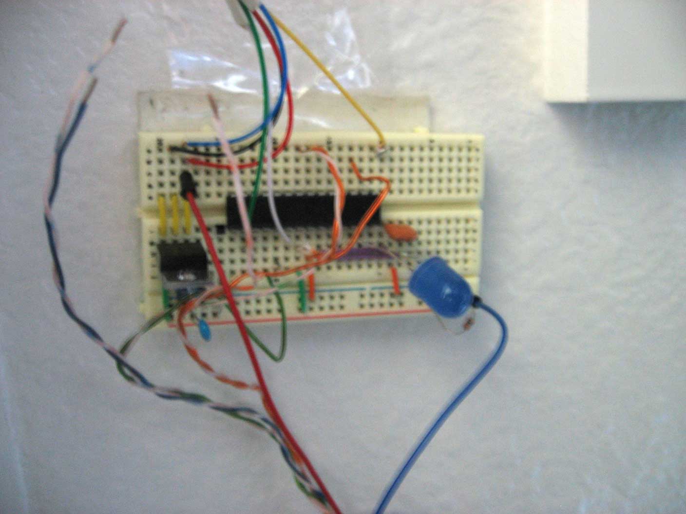
Microcontroller for prototype 2.
My third prototype used an Arduino Nano because it fit nicely on a breadboard and I really liked the integrated USB FTDI programmer. There would be no more connecting UART wires from my Duemilanove to program the bare ATmega328 chip on the breadboard. (Fall 2012)
My fourth and final prototype (Fall 2013) used something completely different: an Electric Imp. I switched to this microcontroller because I wanted practice writing a real program for the Electric Imp platform, I wanted my lock to report to the Internet, and the I/O count for this circuit was incredibly low. (only four pins necessary) The only disadvantage to using the Electric imp is that the lock sometimes does not work when the Internet connection is down.
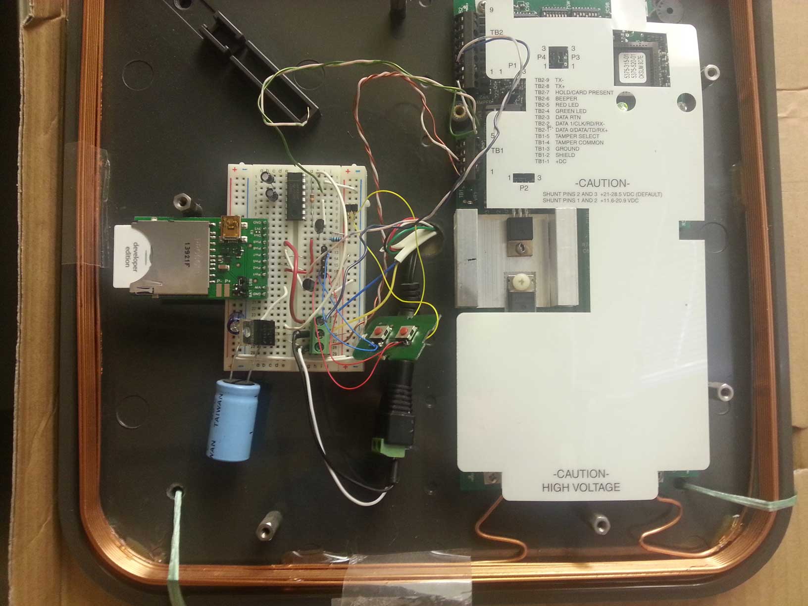
Prototype 4. Uses an Electric Imp instead of an Arduino. MOSFETs and MAX232 are level shifters. Giant capacitor was for troubleshooting an Arduino freezing problem detailed in “Problems encountered” section.
Input Device
My circuit needed two inputs:
- Authenticator
- Door open/closed detector (only necessary for deadbolt)
The authenticator could be anything. I saw builds online where people used twelve-button keypads, keyboards, secret knock sequences, text messages, and Hack-a-day’s RGB pad. The most fascinating one to me was the single button entry system in which you have to input almost morse code-like sequences by pressing your doorbell a number of times, then wait. It was discreet (nothing showing on the outside) and relatively cheap. The circuit was also interesting because on the other side of the doorbell you receive morse-code modulated AC, which you have to rectify and regulate to logic levels for the microcontroller. Interestingly, I chose none of the above because they were just not as quick and easy as holding an RFID proximity card to a reader.
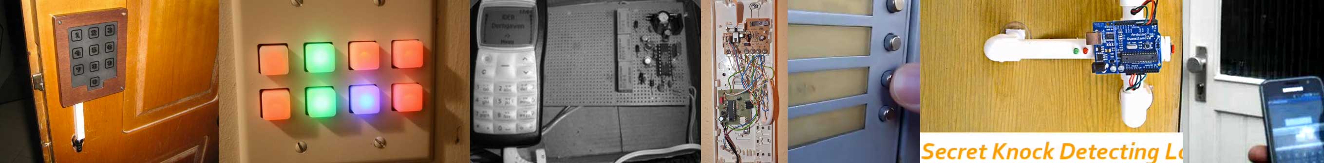
A bunch of different authenticators. Left to right: Twelve-button keypad, RGB keypad, Cell phone, Morse code doorbell, secret knock detector, iPhone app
For the proximity detector, I didn’t have many choices. I read about “active RFID”, in which RF tags have batteries that each user carries, but I read that this was expensive and I could not find a place to purchase tags/base stations. The modern day equivalent to “active RFID” is called “Bluetooth 4.0 Low Energy” (BLE). It detects whether two radios are in a fifty foot range. This is what Lockitron and all of its competitors use today. The user does nothing but walk up to the door. However, there was no BLE in Fall 2010.
Even if I did have Bluetooth 4.0 though, I would still had the problem of “how do I prevent the door from unlocking when I am on the inside?”. The Kwikset Kevo lock claims to solve this problem with “inside/outside technology”, whatever that means. Maybe they have some kind of metal reflector.
Proximity detector
My first proximity detection device was a Parallax RFID reader (model 28140) that read standard EM4100 tags. However there were a few problems:
- My roommate and I had to carry special RFID tags in our wallets.
- The baud rate of the reader was hardcoded at an extremely slow 2400 baud so there would be a delay between reading and unlocking.
- The read distance was three inches maximum.
- There were all kinds of tutorials online about how to fake these tags.
Unfinished prototype zero with Parallax reader and buzzer since the Parallax reader doesn’t beep like the HID readers.
These restrictions eventually led me to change the RFID reader to an HID Thinline II that I bought from eBay. Now my roommate and I could just press our school IDs against the door AND the tag reading process was much faster with the Wiegand interface. In fact, with a second RFID reader, I had nothing to do with the first two tags. I ended up using them as secret lockout tags that you had to present to the card reader in the right order to open the door.

Parallax reader and awkwardly shaped tags. You have to present the V and C tags in the right order to unlock the door! Fun!
The HID Thinline II was nice, but it did not solve the small three-inch read distance issue. We still had to press our tags to the door. I solved the read distance problem by setting up a eBay alert for the ultimate RFID reader– the HID Maxiprox, for use with parking lots. It retails for $400 but has a read distance of twenty four inches. This allowed me to read through the wall. If placed correctly, this meant I would not even have to take my wallet out of my pocket. In addition to this amazing read range, it was physically large enough to contain some DIP switches for conveniency settings like “beep on or off”, “power from 12 or 24V”, “Wiegand/RS-232/RS-422 interface” and a few others. You could not believe my excitement when I scored this industrial equipment for $13 at an eBay junkyard sale.

Size comparison between the HID Maxiprox, Thinline II and Parallax. How many Thinlines could you fit into that Maxiprox? Six? Eight?
For my situation(s) where I conveniently have an alcove for a person to walk into and have their pocket scanned and all users carrying cheap tags in the form student IDs, the HID Maxiprox reader was the best solution. For places without the alcove and student IDs like my home, BLE is probably a better option if you can’t wire an RFID reader, can wire the BLE module and use smartphones with BLE support or can afford $20 tags.
Door open/closed detector
When it came time to control a deadbolt, I needed some way of detecting whether the door was closed or not. I was not under any design constraints, so I had a wire run to the door leading to a magnetic reed switch. The switch is closed if the magnet is near it. This is about as easy as it gets when it comes to write software for it; it’s just a pullup resistor and a pin read.
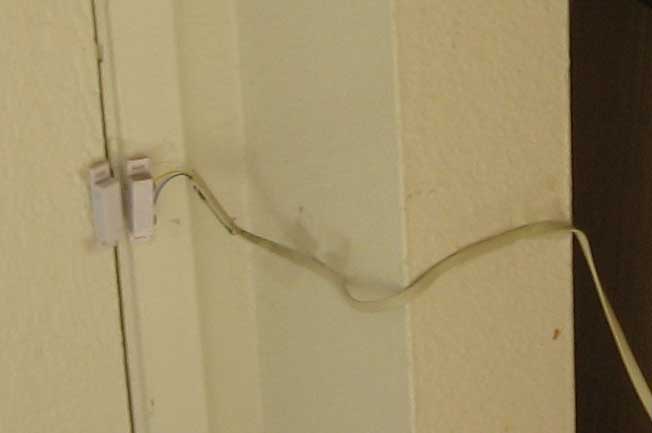
Magnetic reed switch with wire leading to door. Very simple.
What makes Lockitron and all the competitors interesting is that they are obviously constrained by design. It is not an option to have a large wire and reed switch sticking out of their product. I still do not know how they work, but I did speculate:
They might use a time-based rule like “thirty seconds after the door is unlocked, lock it”. This is easiest to code but then your deadbolt can lock while the door is open and you don’t get the satisfaction of knowing your door is locked immediately after you close it.
Lockitron has a “knock sensor”, which I am guessing is an accelerometer. Theoretically, they could write some really smart accelerometer analysis code that correlates with a known “door closing” acceleration pattern. That would be impressive.
Output Device
Lock actuator
The most important part of an electronic door lock is the lock. Fortunately, I never had to actually engineer a lock; just actuators for the lock.
Servo motor
For my first prototype in the dorm, I was working with a heavy duty mortise lock that had its own microcontroller. Obviously my first thought was to trigger it electrically by applying a voltage to some pin and hopefully unlock it. However, in my disassembly process, I found out the hard way that if you disconnect power from the microcontroller, it loses all of its configuration data. I had to ask access control to reprogram both me and my roommate’s card info into the lock. For this reason, I decided to go mechanical.
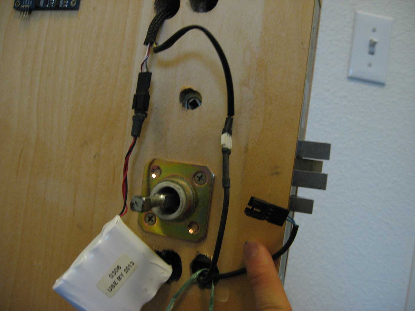
Disassembling the door lock to tie the string. Surprisingly, I never lost power with the battery dangling like this.
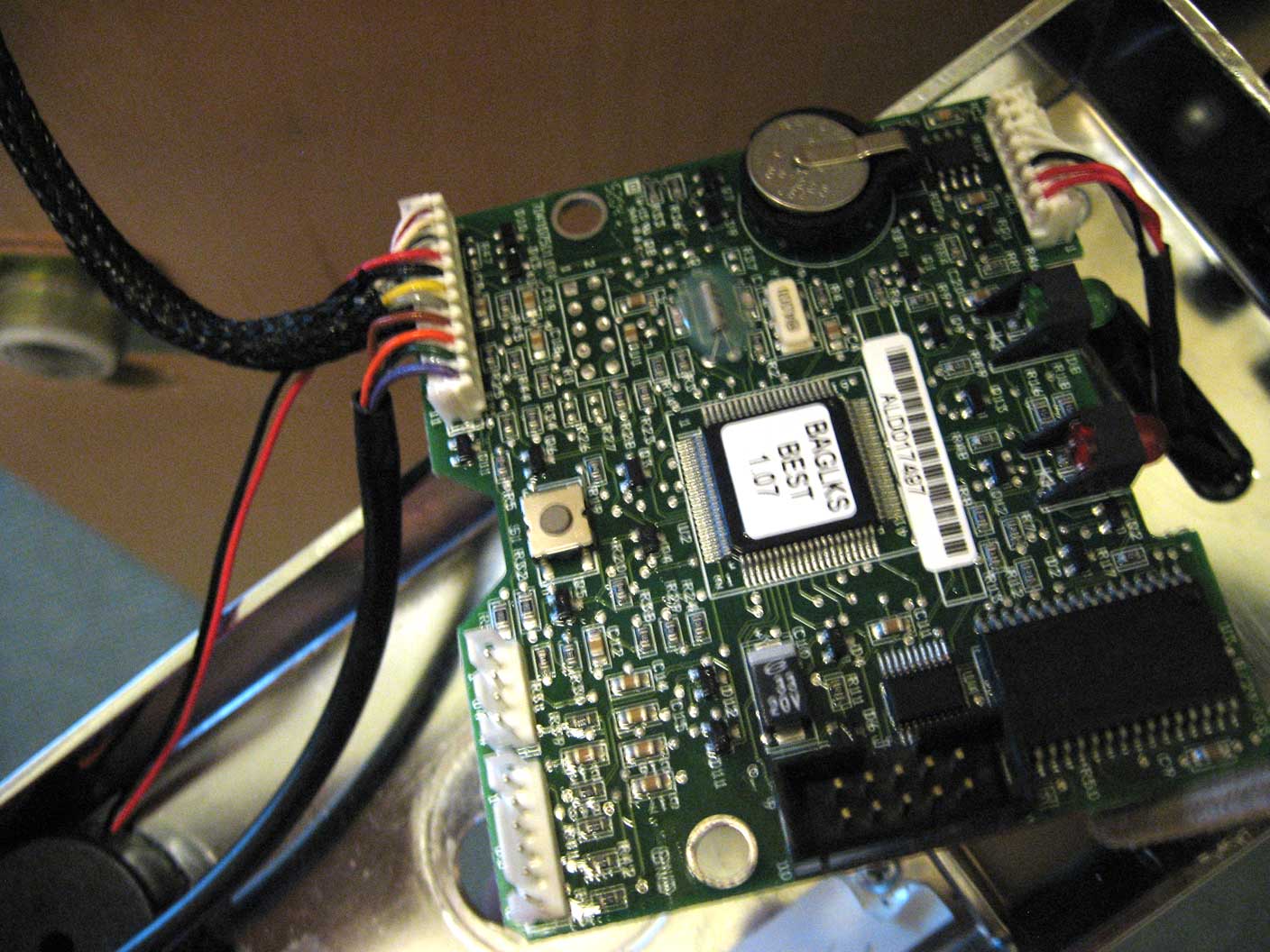
The PCB inside the door lock, featuring four magic ICs. I probably lost power at this stage.
(However, if I were to do this today, I would go electrical. I found a solenoid in the lock, but you had to apply a voltage one way to pull and then a reverse voltage to push and at the time I had no idea what an H-bridge was. It also required a soldering iron, which I did not own at the time)
My first prototype used a bottom-of-the-line HS-311 servo motor tied to the mortise lock with very strong plastic string under a lot of tension. I used string because I was under the restriction of not drilling through the door. I had to disassemble the mortise lock a little but eventually I tied the servo down enough so that it would not budge.
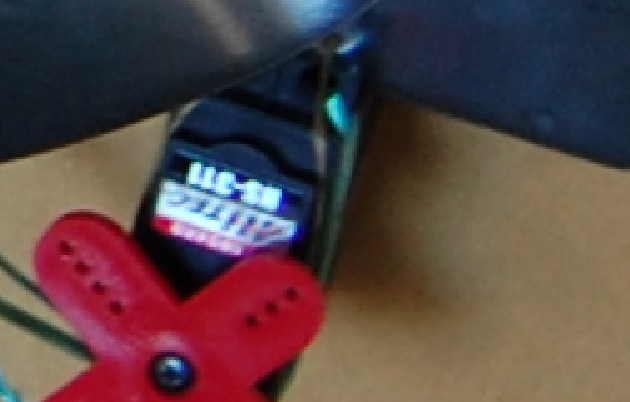
Close up of of the servo attachment. Notice how the twine is going INTO the lock case. I had to tie a lot of knots inside the case.
Morning Industry Deadbolt
In my apartment, I tried to go the same route with the deadbolt. I bought two really big 3 lb 24V solenoids that pulled string looped around my deadbolt and tied the solenoids to the door hinge. I wish I had a picture to show. Unfortunately though, it looked really tacky and I could not achieve both manual control and have the string under enough tension for the solenoids to pull the deadbolt.
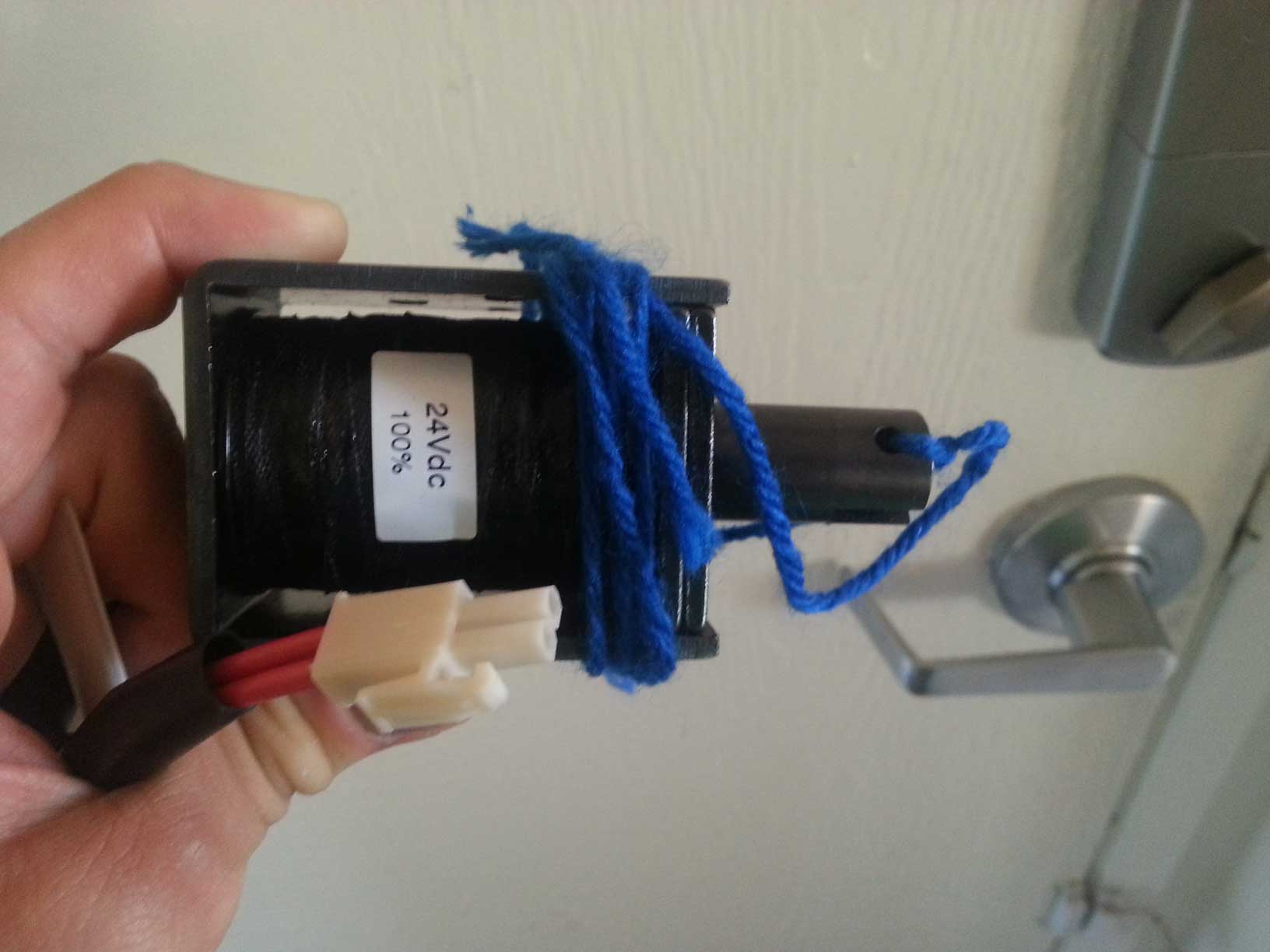
Gigantic 24V 100% duty cycle solenoids that I wanted to affix to the hinge of the door so that they could pull the deadbolt open. Uses string to keep the bolt in place.
I saw a video of an “X10 deadbolt” online. It used an iPhone app and X10 plug-in relay modules soldered to a Morning Industry deadbolt remote. The X10 relays would activate the remote and the door would unlock.
I really liked this idea, so I decided to shop for a remote control deadbolt. The lowest-priced RF deadbolt I found was a Morning Industry RF-01SN for $84 shipped. At the time of this writing, it is still selling on Amazon for $89 shipped. (archived page) I used this lock in prototypes three and four.

Morning Industry Deadbolt Box
“Oh, you just threw money at the situation–anyone can do that”, you may think. But no, you would be wrong. I had multiple problems with the lock that I detail in the problems encountered section.
Solenoids
I actually did this project at home in San Francisco as well. Surprise! Or maybe not. At home, there were actually two doors and hence two keys to suffer through, so there was even more benefit to be realized. The first door already had a solenoid on it too, so no jerry rigging an actuating mechanism was necessary. The second door though did not have a solenoid, so I took some measurements and added one.
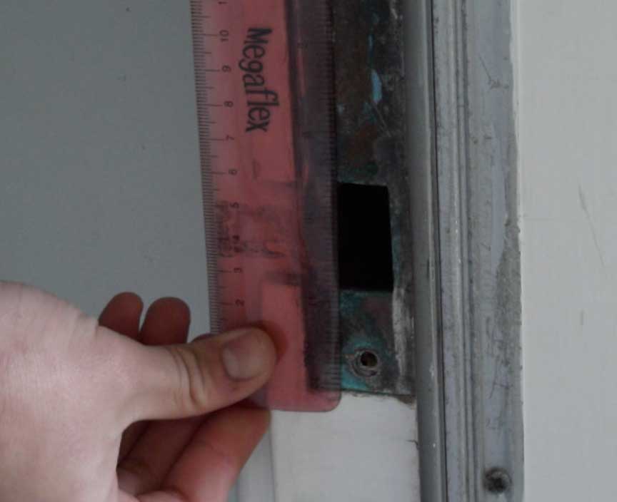
Taking measurements
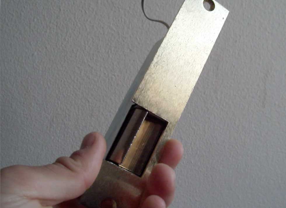
The solenoid I selected. It fit almost perfectly.
One aspect I really didn’t like about residences vs commercial buildings was that residences are cheap and buzz with low-voltage AC when you press the “door open” button. At commercial buildings with their high-tech access systems, the relay and solenoid will “click” open elegantly with DC, making it more pleasant and easier to open the door since the solenoid pin doesn’t vibrate back and forth.
I wanted the elegant DC click, so I used a multimeter to figure out the house wiring. I actually slowly destroyed the multimeter in the process because I was trying to run continuity tests on a live 24VAC circuit (33V peak). I didn’t know the multimeter was being destroyed when it was buzzing, but it told me what I needed to know! I rewired my house such that my relay circuit could inject DC into the existing wiring. Now I had the nice click.

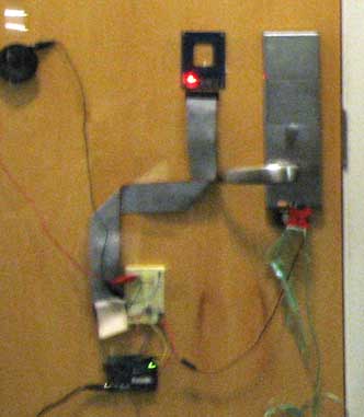
Fun figuring out house wiring. Notice the breaker box and step down transformer on the left. The grey wires lead to the first door solenoid.
When I was done with all the drilling and wiring, I modified my prototype 1 program a little and it was complete! I was so proud of it that I presented the access cards to my family in the form of wrapped gift cards.

The best gift ever! No more keys!
Internet Logging
For internet logging, I also had multiple prototype iterations! Prototype three had a whole chain of devices that worked together to report to the internet: the Arduino Nano used the X10 library to both turn my lights on when my card was scanned and to talk to a PSC05 Two-way Powerline interface > Wall > PSC05 > Arduino > ENC28J60 ethernet module > PHP page > MySQL database. To look up the database, I would have to open PHPmyAdmin on my hosting account and see the database entries. Furthermore, they would just be numbers that needed to be translated into actual roommate names. And the code for the ethernet module was incredibly ugly and hard to understand.
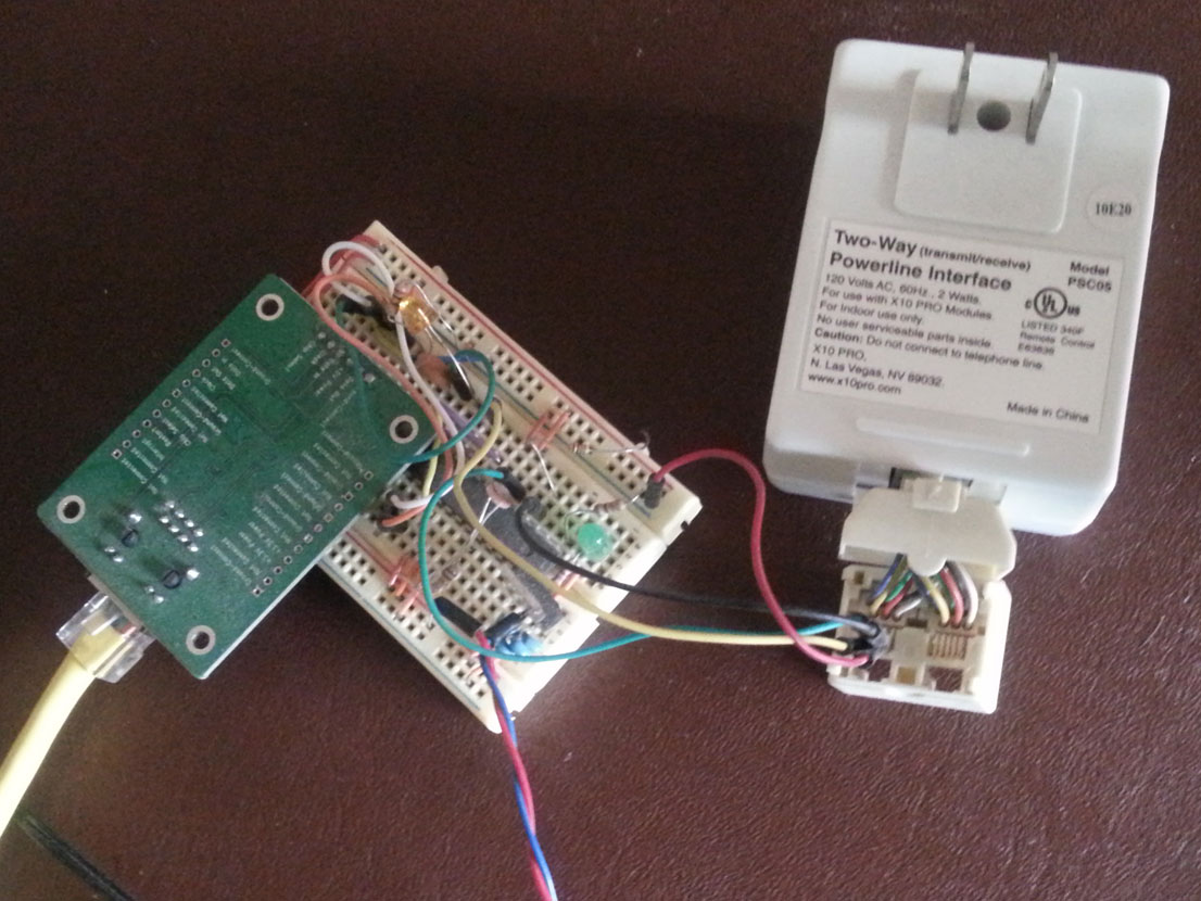
Old internet gateway with Arduino receiving X10 commands and sending HTTP GET with ENC28J60. This was REALLY hard to program and required a hosting service. So ugly.
Obviously, this chain was way too long and had several points of failure, so in prototype four, I replaced it with the Electric Imp and the Xively cloud. In fact, the I/O count was so low that I decided to replace the entire Arduino with the Electric Imp. Because it was so easy to work with, I was able to spend time to write a front end webpage with a javascript timeline module that updates in realtime!
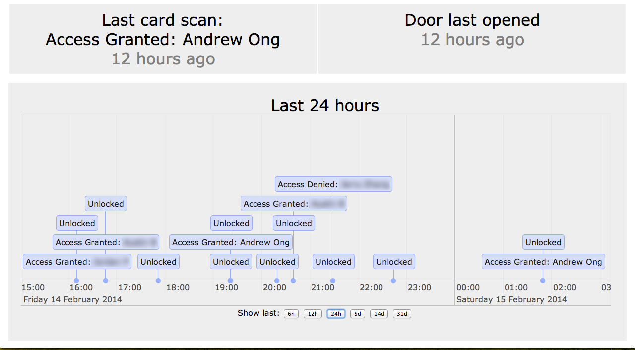
Dynamic front-end with zoomable timeline and some light CSS. I was modern and used <div>, not <table>!
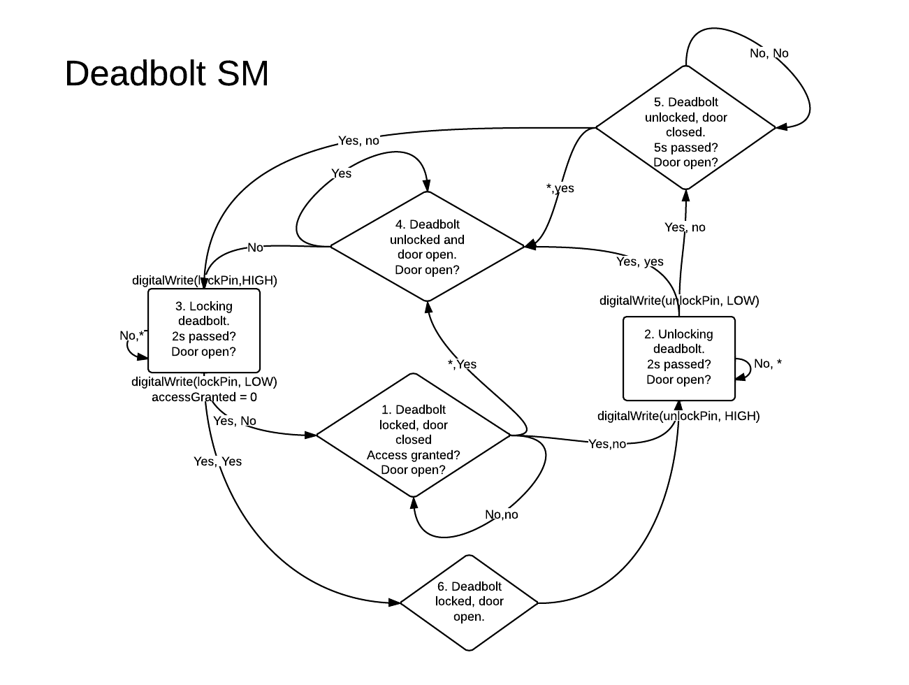
State Machine
The code for all prototypes including the one at home was very similar. Prototypes 1-3 all used a bunch of if statements that were hard to understand as a whole and missed corner cases. Only in prototype four did I finally use a state machine for unlocking the deadbolt.
Code
The code for prototype four on the Electric Imp is on Pastebin (agent/device). I don’t want to share the ugly hodgepodge of if statements I had before the state machine.
Schematic
This is the schematic for prototype four. All the others are very similar.

Problems Encountered
Morning Industry Deadbolt
Requirement four was that the lock still needed to be accessible to housing administration. This meant that I had to merge the back of the Morning Industry (MI) lock with the front of the Schlage lock that was already there. When I tried to place the Schlage mounting screws in the MI backplate, they didn’t fit. I had to request that my machine shop friend actually make the holes wider.
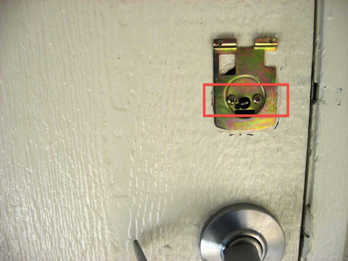
These backplate screws belonged to the Schlage lock and originally did not fit.
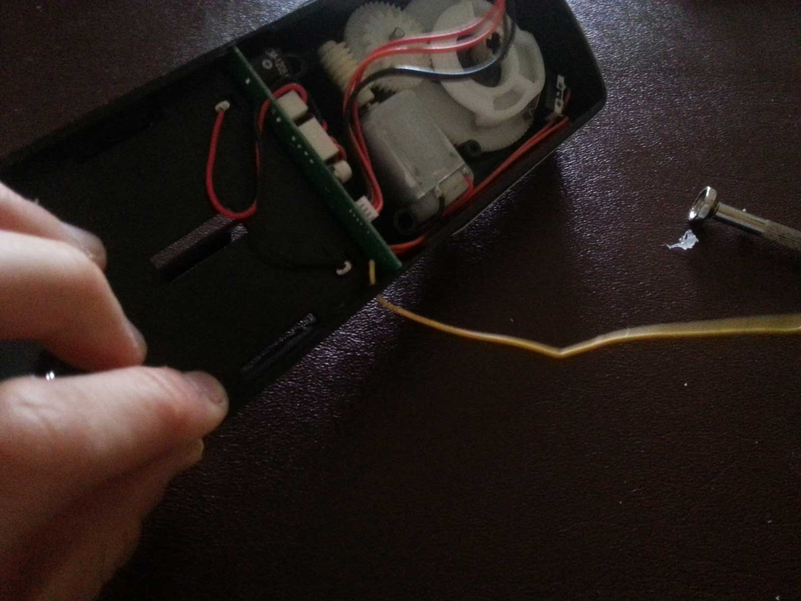
I had to disassemble one of the remotes and solder very thin wire to the PCB to power it and access the buttons. Then I had to figure out how to use it. At first I used relays, but later found out that I could simply tie one side of a button to a microcontroller I/O pin and output HIGH to activate it while always leaving the other side floating. So no more relays necessary.

Left: remote. Middle: Battery. Right: disassembled with wires soldered to it.
Lastly, the RF aspect had reliability issues. It would only work about 80% of the time, which was absolutely unacceptable. In prototype three, despite the Arduino activating the remote at a distance of only two feet away, the deadbolt would not receive the signal. I speculated it could be because of the proximity to the fridge, but I could not change this. Instead, I unmounted the MI deadbolt and identified its wire antenna. With the help of my roommate, I was able to drill a hole in the side of the case, color the antenna black and route it outside of the satin nickel Faraday Cage case. I wish I could quantify the increase in sensitivity in dB. The result of this was that the deadbolt now received 99% of the signals sent from two feet away.
Unfortunately, even after this, the antenna still sometimes fails to receive. I found that shoving the lock back and forth fixes the issue.
Pulling the antenna outside of the case

Antenna, now colored black, sitting outside of case with much better reception.
Deterioration from weather
At my home door lock, I needed to run a lot of wiring. It became really tedious making all the connections, and two years ago I had no soldering iron. My prototype worked but it failed after a few months because the wires became loose and corroded. I eventually created boxes for all the electronics.

Wonderful dangling relay module. Very reliable.

Much better enclosed relay module and soldered connection board. Also uses ethernet wire instead of ribbon cable. Has lasted for multiple years.
Arduino Freezing
I had the strangest issue where the Arduino would just freeze, and not from an infinite loop either. It would freeze before I even had a chance to issue at DDRC |= 0x01 command at the beginning of the setup function. It would only happen occasionally, but when it did happen it was very frustrating because I would have to take out my keys. I speculate it had something to do with a bad power supply and being next to the fridge. I partially solved the problem by adding a gigantic decoupling capacitor on my breadboard (100 uF). I sealed the problem away by enabling the Arduino’s watchdog timer. When I switched to the electric Imp and lost my watchdog timer (I assume they use it on a lower level), I expected this issue to reappear. It hasn’t so far.
Fridge and Exhaust Fan
Sometimes the MI lock beeped twice as it does when you tell it to lock but it’s already in the locked position. About once every three days, I notice that when the fridge turns off or the exhaust fan above the stove turns off, prototype three would cause the lock to beep. Prototype four still does for the fridge (extremely rarely) but not for the exhaust fan anymore. This is kind of hard to reproduce, but I believe it is because of noise being picked up by very long wire that is connected to the reed switch when the fridge compressor turns off. The reason we use “pull up” switches is so that noise has a path directly to ground in the event that this happens, but the phone wire I used for the reed switch is very thin, probably making it a good high-impedance antenna. In any case, it does not affect operation in any significant way.
Potential Improvements
All of the prototypes are incredibly messy with wires everywhere. They would cosmetically benefit from a PCB. However, until 2012, PCB was not even in my vocabulary. The circuit never moved, was not being mass produced, was being revised constantly and already had PCBs in it. That is why I never made a PCB.
There are some features in Lockitron that my lock does not have. Specifically:
- Offline support – By default, the electric imp suspends and does nothing whenever the Wi-Fi connection drops. I only recently learned that it is possible to program the imp to not suspend and work while offline.
- Knock detection and alert – this would be nice to have but would require an accelerometer mounted on the door.
- Bluetooth 4.0 (but I cover why in the Input Devices section)
- Remote unlocking – I have never wanted this in two years, ever. Though now with electric imp, it would be really, really easy to add.
- Scheduled/temporary access – I would only use this for housing staff, and they already have keys.
- Battery Life Indicator – I believe the MI lock will beep when the battery is low, but I have never encountered this issue. The RFID reader and Electric Imp are plugged into the wall.
- Goji: snaps picture of person someone knocking at door. This is very impressive because it would require a camera on the door. This would also require a much beefier microcontroller. I read this thread and it said the Electric Imp with its 80k of memory can barely hold one 47k JPEG picture with a special compression library. Who knows if 47k is even enough memory considering everything else on the imp. Furthermore, the bandwidth was not meant for sending 47,000 byte messages I’m sure.
I could also upgrade my HID reader to an more modern, encrypted 13.56MHz iClass reader to replace the unencrypted 125KHz one I have now, but I would A) have to have all my roommates carry extra cards again and B) find a long range iClass reader. Maybe at home.
Conclusion
I assembled a door lock that satisfied all of my requirements, that was actually better than Lockitron for my situation (again with the BLE vs RFID). My costs for all parts in prototype four totaled to about $145 + time. This is good considering prototypes typically cost more than mass produced products, but if Lockitron was out there two years ago, I would have seriously contemplated just paying the extra $34.
Of course if I had just purchased Lockitron, I would not have learned about:
- Arduino watchdog timer
- Electric Imp platform
- low voltage (24V) AC household wiring
- Xively: how to use a REST API with JSON
- X10 home automation control with Arduino!
and would not have had practice with
- Making a two-input state machine that wasn’t a homework assignment from CS61 (and CS120A…and CS120B….)
- HID RFID readers and decoding ASCII-encoded hex and bitshifting

Your genius man, love your blogs. Are you a web designer or you do this stuff just for fun?
Thank you for the compliment. I’m not a web designer, I just knew that I had to use HTML, CSS and Javascript to make a pretty and dynamic webpage. I do all of this for fun. Practical fun.
bro i need this for a project could you please help me out by sharing a detailed report and analysis on how you did step by step, it would help me a ton
bro you are asking for too much. If you have a specific question then that’s easier to reply to than “I need a detailed report”.
Love your ideas and videos! Have you got anything else planned?
I could really use an idea or two. I would really like to do a video on control systems. I would also really like to do one on DSP. I just don’t know how to make these visually interesting and practical.
This is awesome! and that’s exactly what im working on, but much more simpler, im not advanced as you 🙂 i got the same electronic lock and electric imp. Trying to figure out how to push a signal from the imp and send it to RF remote to trigger the button, no luck yet. have you finished your project?
I consider the project to be complete. My roommates and I used it for months and it had a 95% success rate. The only significant problem was the reliability of the RF commands reaching the lock. The next step would be to redesign the lock and commercialize it to be an Internet-enabled product. That’s where Lockitron, Goji, August and Kevo come in.
Good luck with the Imp to the remote. As my roommate said, “I’m not impressed by the lock, I’m impressed that you made it.”
Reblogged this on Jason's Blog and commented:
ignore this post
Hi, I am building the lock from the scratch, are you able to tell me the exact sizes of 2 gears that are used in Morning Industry RF-01SN bolt you used ?
I never built the lock from scratch despite the title of the Youtube video. I don’t know the specifications of the motor or the gears.
Also the specs for the motor that is inside, thank you !
are you able to measure the size of the gears ?
I would have already, but I don’t have the lock anymore. I left it in the school apartment.
Ok, thank you anyways. Btw, great project. It helped me a lot with my idea 🙂
Hello, I’m trying to replicate your Morning Industry RF-01SN project and was looking at the way you had the remote wired up. I popped open one of the remotes, and it appears to have two 3v batteries in series. Making the input voltage 6v? I assume the remote itself uses 3.3v logic though according to the way you have it wired in your diagram. However your diagram also shows only 3.3v and ground going to the remote. Did you connect your leads for the remote to the battery pads on the board? I know this was an older project and you might not recall but I thought I would try. Thanks for any help you can provide
Sorry about the long time for reply. Yes. I soldered leads to the battery pads on the board.
Hello, This is John from Scyan Electronics. You have some great Idea for door lock. My company make fingerprint door lock. We may work together to make great locks. Hear from you soon.
Regards
John
Hello, It’s a very good project and very interesting. Do you finished your prototype? If you are looking for investor in EU, I will enjoy to discuss with you.
Regards,
Frederic
Pingback: [Teaser 1]Ultimate Home Automation at Best ATL| Google Assistant Controlled appliances using ESP8266 | Appliances Sale
Pingback: Transform Your Business with Microsoft IoT in Action Webinar Series | Microsoft Home
have you tried this with a rasberry pie? if not, why?
a raspberry Pi would be total overkill for this application and would actually perform worse because Linux might hold up operations.
Could you please send me the CSS and Javascript to make a your dynamic webpages?
I made an automated homebrew setup (see my webpage) but I was using Labview for that.
Thanks
https://www.dropbox.com/s/pbvhi83gz3wkur4/electric-imp-door-lock.zip?dl=0
The frontend was made with some PHP and triggered from the Xively API, which I don’t think exists anymore. In the video you can see how it worked but I think it would have to work with it to get rid of all the errors.
Pingback: Repair non working buttons on Sony TV remote | Television Tech
Very good 👦 idea
How door is opened with a key? There is a worm gear in the lock which can be turned from motor side only…
the lock has a mechanical mechanism to allow the deadbolt to move without the wormgear turning. In addition, the lock has switches to detect the angular position of the deadbolt so the circuit knows if the door has been locked/unlocked already before it turns on the wormgear
Thank you for your answer. I wonder how this mechanism works?
On the pictures above, I assume that deadbolt is moved by non-circular gear. But how a clutch between biggest gear and non-circular gear works?
Thank you for this awsome project
How they work as battery powered with ardunio ? Which component did you use for low power card detection.
I used an HID Maxiprox connected to the wall power